BTI engineers and manufactures a complete line of manual, semi-automatic, and fully automatic industrial surface measurement systems for all part types and sizes, as well as all production rates and levels of automation.
Surface measurement systems inspect the condition of a finished surface rather than its size or position. On a journal, a seal land, a bore or a raceway, the dimension can be dead on print and the part can still fail in service because the surface texture is wrong — too rough to seal, too smooth to hold oil, or carrying a lay direction that pumps lubricant out of the joint instead of retaining it.
Balance Technology builds automated surface measurement systems for production environments: single-station gages that check one feature, and multi-station systems that check several surfaces on a part in one cycle. These are not laboratory instruments moved onto the plant floor. They are built to run every part, at line rate, with operator-proof loading and automatic pass or fail decisions.
What Surface Measurement Actually Measures
Surface texture is described by a family of parameters, and which ones matter depends entirely on how the surface functions.
Ra — arithmetic mean roughness. The average deviation from the mean line. The most widely specified parameter and the most widely misused one, because two surfaces with identical Ra can behave completely differently in service. Ra tells you roughly how rough a surface is; it tells you almost nothing about its shape.
Rz — mean peak-to-valley height. More sensitive to individual peaks and valleys than Ra. Often specified alongside Ra where isolated defects matter.
Rq — root mean square roughness. Weights larger deviations more heavily than Ra. Common in optical and sealing applications.
Rpk, Rk and Rvk — the bearing area family. These separate a surface into the peaks that will wear off during run-in, the core that carries the load in service, and the valleys that retain lubricant. For a cylinder bore, a cam lobe or a bearing journal, these parameters describe function in a way Ra cannot. A plateau-honed bore with a small Rpk, a stable Rk and a generous Rvk performs very differently from a turned surface with the same Ra.
Rsk and Rku — skewness and kurtosis. Whether the surface is dominated by peaks or valleys, and how sharp those features are. Useful for distinguishing a correctly honed surface from one that has been over-brushed or smeared.
Waviness and lay. Longer-wavelength form error and the direction of the machining marks. On a dynamic seal surface, lay direction is critical: a ground journal with residual helical lead from the grinding process will pump oil along the shaft and leak, regardless of how good the roughness numbers look. Lead measurement is a specific and frequently requested capability.
Why It Belongs on the Line, Not in the Lab
Surface finish is almost always a symptom of tool condition. A dull grinding wheel, a loaded hone, a worn insert, a change in coolant concentration — each shows up in surface texture before it shows up in a dimension, and often before it shows up in a scrap part.
That makes surface measurement one of the most valuable process control signals available, but only if it is measured frequently enough to act on. A sample pulled to the lab once a shift tells you that something went wrong somewhere in the last eight hours. An in-line gage measuring every part tells you the wheel needs dressing now, before the parts behind it are compromised.
The counterargument is cycle time, and it is a real one. Surface measurement takes time, particularly on long traverse lengths. Part of designing a system is deciding how much of the surface actually has to be characterized to control the process, and where on the part that trace should be taken.
How Our Systems Are Built
Part holding. The same principle that governs all of our gaging: the part is located on the features the print calls out as datums, and it is held rigidly enough that the stylus traverse does not move it. On a rotating part, the fixture is the same class of workholding we use for dimensional gaging, because a surface trace taken while the part shifts is noise.
Probe positioning. Servo-driven axes bring the probe to the specified location on the part, with the traverse length and direction set by the part program. Where several surfaces are measured, the probe indexes between them automatically.
Measurement. Contact stylus profilometry for most applications, with non-contact optical measurement where the surface is too soft, too delicate, or too inaccessible for a stylus. The choice depends on the surface, the parameters required, and the standard the specification is written to.
Filtering and evaluation. Surface parameters are meaningless without the filter conditions that produced them. Cutoff wavelength, evaluation length and filter type are defined in the part program and applied identically to every part, so that a number measured today is comparable to one measured last year.
Decision and data. Pass or fail against the specification limits, a result record per serial number, and export to your quality system. Trend charting on the gage itself lets the operator see a parameter drifting toward its limit before parts start failing.
Where It Gets Used
- Crankshaft and camshaft journals — roughness plus lead on seal surfaces
- Cylinder bores — plateau honing verification using the bearing area parameters
- Bearing races and rollers
- Sealing lands and dynamic seal surfaces
- Gear flanks
- Hydraulic bores and valve spool surfaces
- Pump and compressor rotor surfaces
- Brake rotor friction surfaces
- Electric motor shaft surfaces and rotor laminations
Combining Surface Measurement With Other Operations
Surface measurement is a natural station on a combination machine. The part is already located on a precise axis for balancing, gaging or crack detection, and a surface probe indexing onto a journal adds an inspection without adding a fixture, a transfer or a load station.
The pairing with crack detection is particularly common, because surface condition and surface flaw detection both interrogate the same few microns of material and are frequently affected by the same upstream process problems. A grinding burn often shows up in both.
What We Need to Design a System
- Part drawings, with the surface specifications and the datums the features are referenced to
- The parameters required, the limits, and the standard the specification is written to
- Filter conditions: cutoff, evaluation length and filter type, if specified
- Where on the part the measurement has to be taken, and how many locations
- Part size, weight and family range
- Required throughput and the takt time the measurement has to fit inside
- Whether the measurement is for acceptance, for process control, or both
- Data export requirements
Frequently Asked Questions
Can you measure surface finish on every part at line rate?
In many cases yes, depending on traverse length and the number of locations. Where a full trace will not fit in the cycle, we design a shortened trace that still captures the parameters you are controlling, or an automated sampling scheme that measures every nth part without stopping the line.
Contact or non-contact?
Contact stylus remains the reference method and is what most specifications are written around. Non-contact makes sense on soft materials, coated surfaces, surfaces that must not be marked, and geometries a stylus cannot reach. We will recommend based on your surface and your specification rather than on what we would prefer to build.
Can you measure lead on a seal journal?
Yes. Lead measurement is a specific capability and one of the more common reasons customers come to us for surface measurement, since a journal that passes every roughness parameter can still leak.
Can you add surface measurement to a machine we already have?
Frequently. If the existing machine already locates and rotates the part precisely, adding a surface station is a rebuild and retrofit project. We do this on our own machines and on machines built by others.
Why do parts that pass Ra still fail in service?
Because Ra is an average and function is not. A surface with the right Ra but the wrong peak structure, the wrong valley volume, or a lay direction that pumps lubricant will fail while reading perfectly in specification. If you are seeing that pattern, the answer is usually to specify and measure the bearing area parameters, and to check lead. This is exactly the kind of problem these systems exist to catch.
Eddy current crack detection systems, surface finish measurement equipment, NVH equipment (noise vibration and harshness), functional test stands, spinners, motor testers, and resonant frequency measurement systems.
We also engineer and manufacture specialized test systems, including torque-to-turn, backlash, end play, and destructive test equipment.
Additionally, BTI’s unique ability to combine the aforementioned technologies into one fully integrated system enables our clients to reduce capital expenditures, increase product quality, and minimize floor space requirements. There is no need for costly conveyors and escapements to connect independent machines together; nor do you need to train operators on multiple machines. There is one seamless, easy-to-use operator interface with unprecedented networking, statistical, and diagnostic capability.
Whether you need a fully integrated, combined technology system (e.g., a balancer/gage/NVH combo) or independent machines, let our team of mechanical, electrical, and software engineers design and build a configured-to-order system for you.
If you don’t see the product you are looking for, or have specific questions, please contact us.
Other solutions
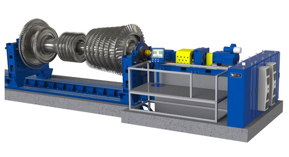
200,000 lb Capacity Horizontal Balancer for Steam and Gas Turbines
200,000 lb Capacity Horizontal Balancer for Steam and Gas Turbines
View More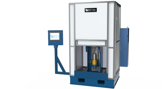
30,000 rpm Automatic Spin Tester for Induction & Permanent Magnet Electric ...
30,000 rpm Automatic Spin Tester for Induction & Permanent Magnet Electric Vehicle Rotors.
View More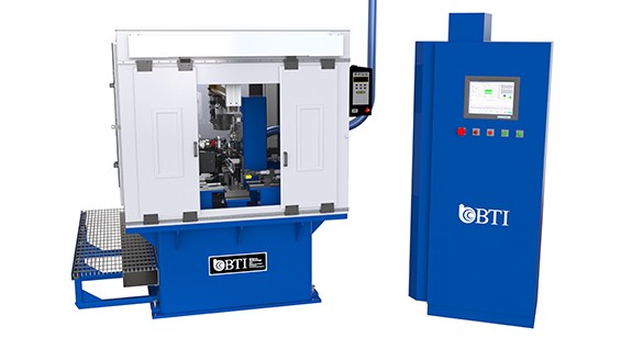
300,000 RPM Turbo Charger Balancer, Wheel Milling
Fully-Automatic 300,000 rpm High Speed Turbo Charger Assembly Balancer with Automatic Compressor Wheel Milling & Drilling Correction. Featuring Servo Controlled Air Drive System, Oil...
View More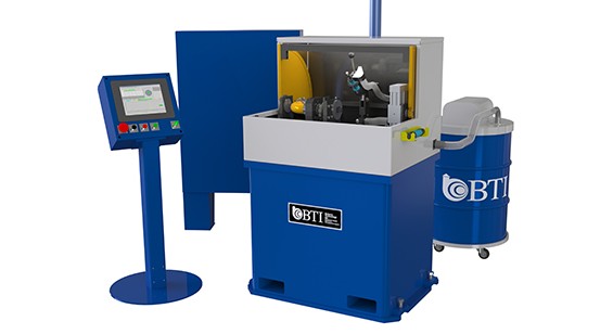
300,000 rpm Turbo Charger Core Assembly 2 Plane Balancer
4,000 to 300,000 rpm Low and High Speed Turbo Charger Core Assembly 2 Plane Balancer with Touch Up Grinder, Featuring Pulsation Measurement & “G”...
View More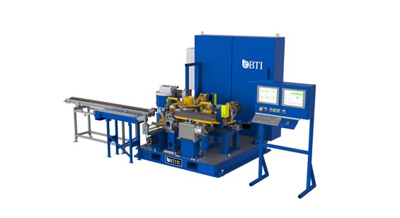
5-Station Armature Balancer with 2 Plane Contour
6-Second (600 part per hour) Fully Automatic 5-Station Armature Balancer with 2 Plane Contour or V-Cut Mill Correction
View More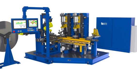
5-Station Torque Convertor Assembly Balancer
Fully Automatic 5-Station Torque Convertor Assembly Balancer with Automatic Variable and Fixed Length Weight Making and Weld Correction, featuring Automatic Walking Beam Transfer, Oil...
View More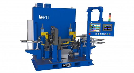
6-Station Armature Balancer w/ Axial Drill Correction
220 Part Per Hour Fully-Automatic 6-Station Armature Balancer Featuring Dual Axial Drill Correction, Walking-Beam Transfer, Overhead Belt Drive and Part Sorting
View More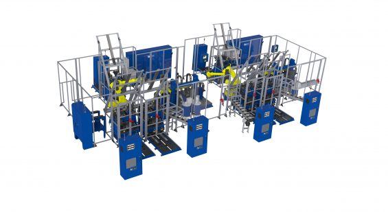
Induction & Permanent Magnet Rotor Cell
Automated Induction & Permanent Magnet Electric Rotor Cell Featuring two 6-Station balancers, six 30,000 rpm Automatic Spin Testers and Four Robots
View More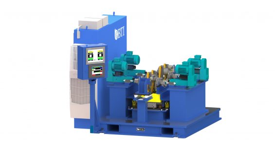
Automatic 2-Station Induction Balance Solution
Automatic 2-Station Induction & Permanent Magnet Electric Rotor Cell Featuring two Independent Balance Stations, Dual Drills on Each Station, Scissor […]
View More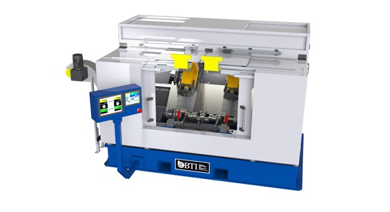
Automatic Crankshaft Balancer with Dual Servo MQL Drill Correction
Fully Automatic Crankshaft Balancer with Dual Servo MQL Drill Correction and Overhead Gantry Load Screen reader support enabled. Fully Automatic Crankshaft Balancer with Dual...
View More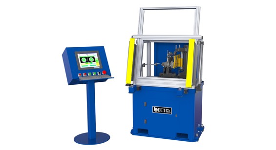
Low Speed Turbo Charger CHRA Assembly Balancer
Automatic Low Speed Turbo Charger CHRA Core Assembly Balancer with Dual Drive Technology, Featuring both Belt and Servo Controlled Air Drive Systems as well...
View More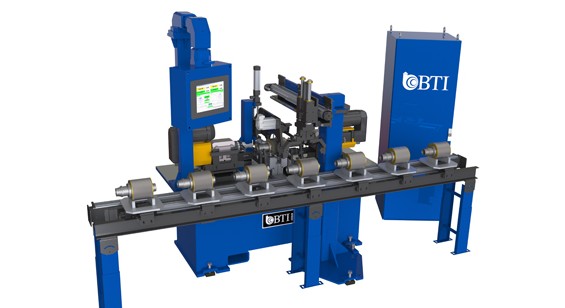
Automatic Permanent Magnet Rotor Balancer
Fully Automatic Permanent Magnet Rotor Balancer, featuring Automatic 2-Plane Axial Drill Correction, Pneumatic Pick and Place Transfer, and Palletized Part Conveyance
View More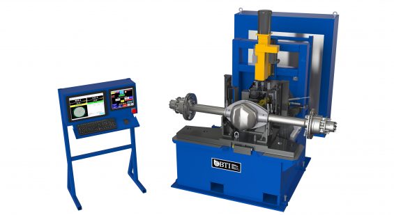
Automatic Rear Axle Balancer With Automatic Drill Correction
1000 lb Fully Automatic Rear Axle Balancer Featuring Automatic Drill Correction and Part Marking
View More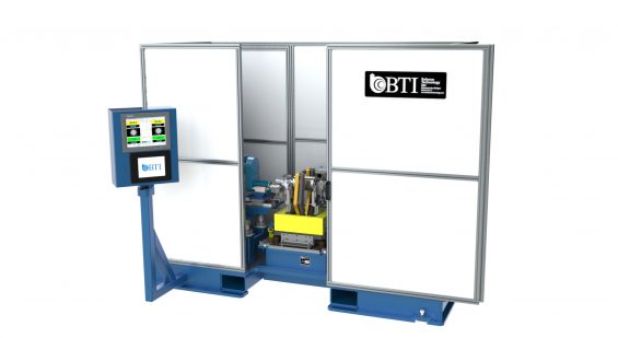
Automatic Single Station Induction & Permanent Magnet Electric Rotor Cell F...
Automatic Single Station Induction & Permanent Magnet Electric Rotor Cell Featuring Dual Drills and Scissor Belt Drive
View More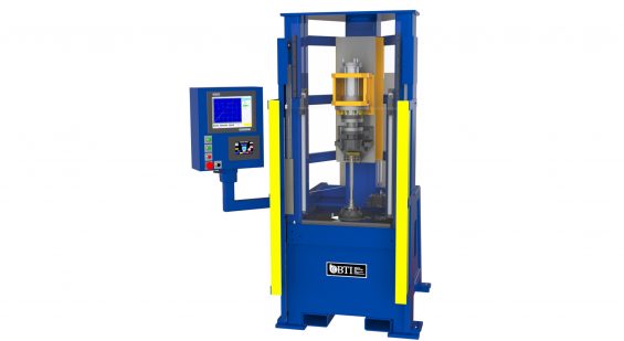
Automatic Torsional Test Stand for Steering Column Tulip Assemblies.
Automatic Torsional Test Stand for Steering Column Tulip Assemblies.
View More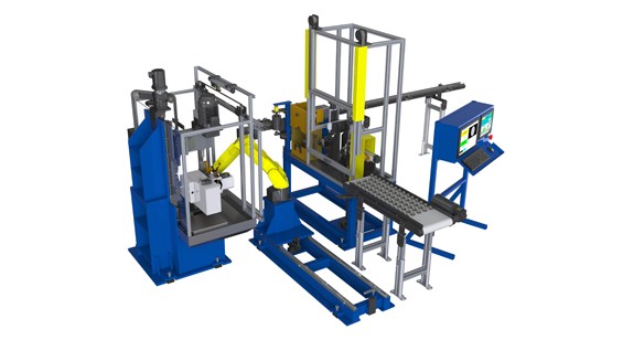
Automatic Turbo Charger Compressor Wheel
Fully Automatic Turbo Charger Compressor Wheel Cell Featuring Automatic 2-Plane Mill Correction, Dimensional Gaging, Eddy Current Surface Defect Detection, 2D Laser Marking, Robotic Part...
View More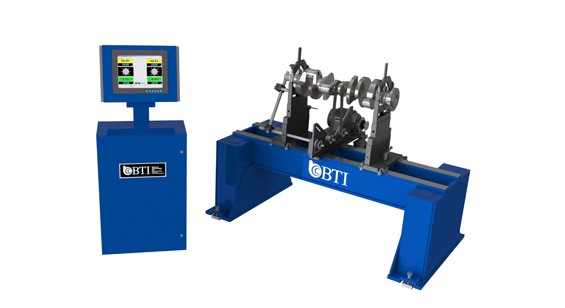
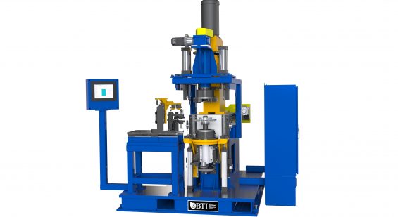
Balancer with Elevator Mill Correction Station
Single station Brake Rotor Balancer with Elevator Load/Unload and Onboard BTI Mill Correction Station. Featuring Dimensional Gaging of Key Attributes such as Flatness, Parallelism,...
View More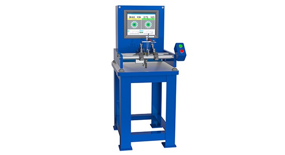
Bench-top Horizontal Balancer for Measuring Unbalance
Bench-top Horizontal Balancer for Measuring Unbalance of Computer Hard Drive Disc Reader Heads
View More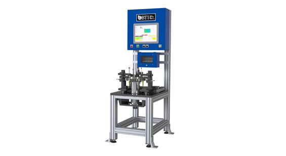
Brake Rotor Bore Gage with Temperature Compensation and Auto Feedback to Upstrea...
Brake Rotor Bore Gage with Temperature Compensation and Auto Feedback to Upstream Machining Operations
View More
BTI’s Patented Spindle-Less CAT, BT & HSK Tool Holder Balancer
BTI’s Patented Spindle-Less CAT, BT & HSK Tool Holder Balancer
View More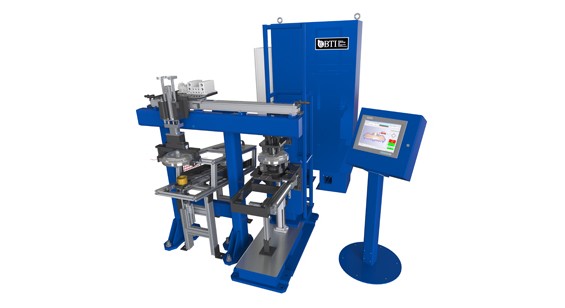
Combination Machine Featuring Dimensional Gaging
Fully-Automatic Combination Machine Featuring Dimensional Gaging and Surface Roughness Measurement of Torque Converter Assemblies
View More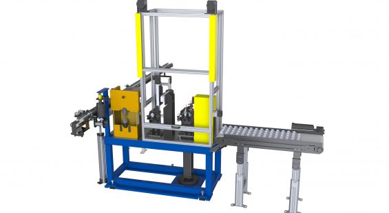
Compressor Wheel Cell Gaging & Surface Detection
Fully Automatic Turbo Charger Compressor Wheel Cell Featuring Dimensional Gaging, Eddy Current Surface Defect Detection, 2D Laser Marking and Conveyance
View More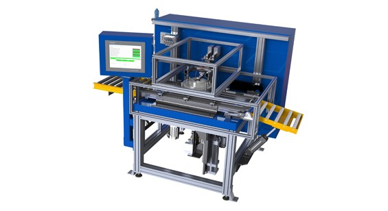
Crack Detection Brake Rotors System
Fully-Automatic Eddy Current Crack Detection System for Brake Rotors
View More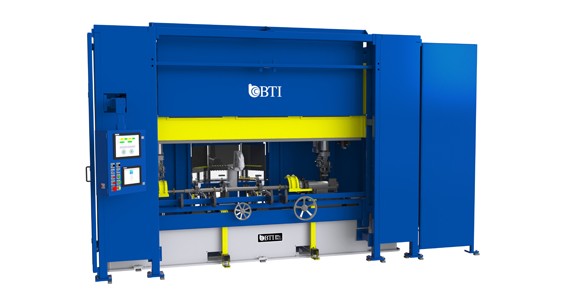
Driveshaft Balancer with Automatic Spot Weld Correction
Fully Automatic 1, 2, and 3 Piece Driveshaft Balancer with Automatic Spot Weld Correction via Magazine Feed Weights, featuring Auto Guard Doors, 5-Plane Balance...
View More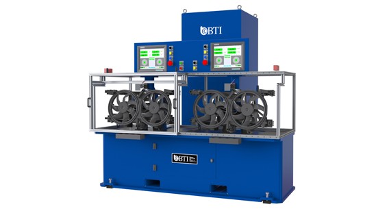
Dual Engine Fan Balancer
Two Station Dual Engine Cooling Fan Balancer Featuring Advanced Blade Counting, Speed and Direction Verification System and Electrical Motor & PWM Function Tests
View More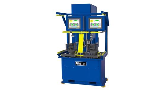
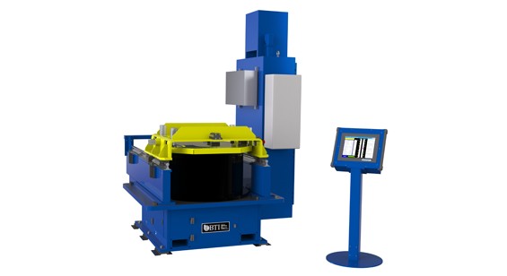
Durability Tester for Grinding Wheels
Semi-Automatic High Speed Durability Tester for Grinding Wheels
View More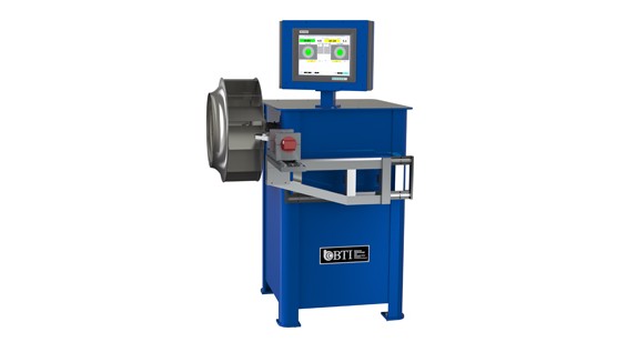
Dynamic Aluminum Fan Balancer with Automatic Rivet Correction
Dynamic Aluminum Fan Balancer with Automatic Rivet Correction
View More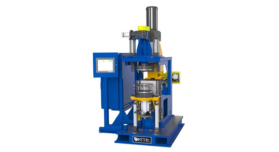
Dynamic Brake Rotor Balancer
Semi-Automatic Single Station Dynamic Brake Rotor Balancer with Automatic Mill Correction
View More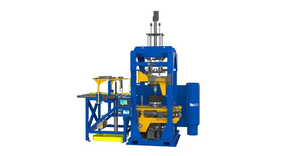
Dynamic Tire Inflator Balancer with Bead Lubrication
Fully Automatic Dynamic Tire Inflator Balancer with Bead Lubrication, Laser Gaging, and Ink Stamp Marking
View More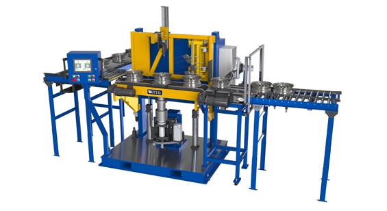
Dynamic Wheel Combination Machine
Fully Automatic Dynamic Wheel Combination Machine featuring Part Identification, Axial and Radial Laser Gaging, and Balance Audit with Orient and Mark
View More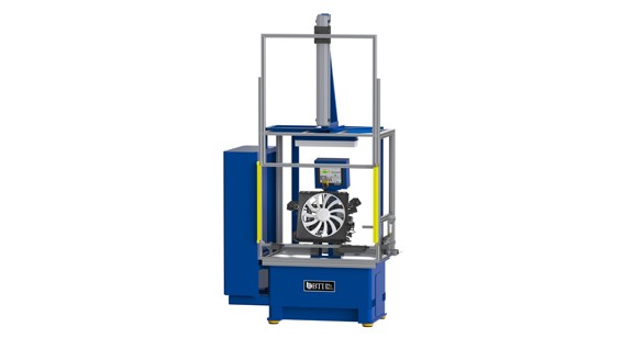
Engine Cooling Fan Module Balancer and Motor Tester
Engine Cooling Fan Module Balancer and Motor Tester
View More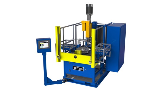
Flywheel Balancer with Automatic Drill Correction
Semi-Automatic Flywheel Balancer with Automatic Drill Correction, Ring Gear Sensor, and Load Assist Elevator
View More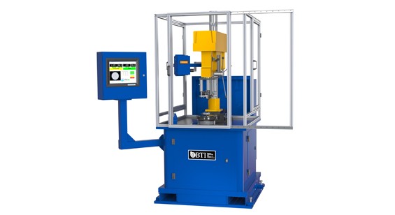
Flywheel Balancer with Manual Drill Correction
Flywheel Balancer with Manual Drill Correction Featuring Drill Depth Readout
View More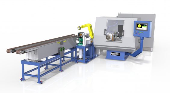
Shaft & Wheel Balancer, Laser Mapping & CBN Grinding
Full Automatic Shaft & Wheel Balancer with Laser Mapping, CBN Grinding, High Pressure Coolant, Ultra-Sonic Part Contact Sensor, Conveyance & Robot Load/Unload
View More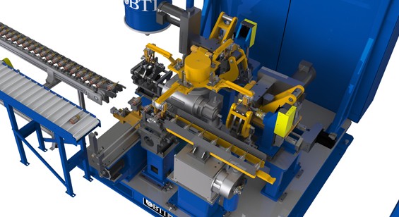
Fully Automatic 5-Station Armature Balancer with 2 Plane Contour
6-Second (600 part per hour) Fully Automatic 5-Station Armature Balancer with 2 Plane Contour or V-Cut Mill Correction
View More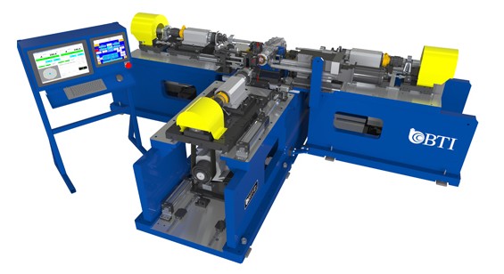
Fully Automatic RDM Balancer and NVH Combination
Fully Automatic RDM Balancer and NVH Combination featuring Drill Correction, Laser Gaging, Drive Shaft Hung Mass Simulation, and Advanced Clutch Conditioning Technology
View More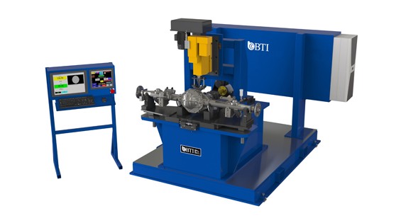
Rear Axle Balancer with Automatic Drill Correction
Fully Automatic Rear Axle Balancer featuring Automatic Drill Correction, Part Marking, and RFID Traceability
View More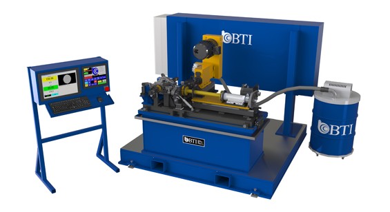
Fully Automatic Rear Drive Module Balancer
Fully Automatic Rear Drive Module Balancer Featuring Automatic Drill Correction, Part Marking, and RFID Traceability
View More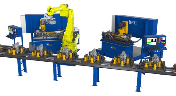
Fully Automatic Rear Drive Module Cell featuring Two Drill Correction Balancers
Fully Automatic Rear Drive Module Cell featuring Two Drill Correction Balancers, Robot with Dual End Effectors, Palletized Part Conveyance, Master Part Housing Stations, Part...
View More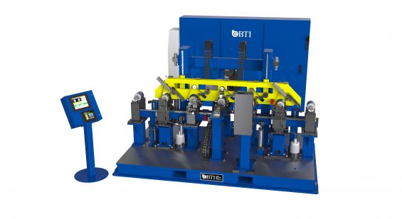
Fully Automatic Six Station Induction & Permanent Magnet Electric Motor Ro...
Fully Automatic Six Station Induction & permanent Magnet Electric Motor Rotor Balancer Featuring Overhead Belt Drive System, Two Drill Correction Stations, Chip Containment and...
View More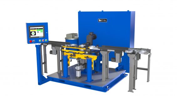
Fully Automatic Stator Balancer with Mill Correction and Walking-Beam Transfer
Fully Automatic Stator Balancer with Mill Correction and Walking-Beam Transfer
View More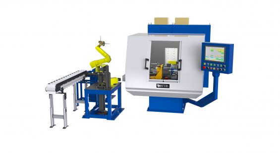
Fully Automatic Turbo Charger Shaft & Wheel Cell
Fully Automatic Turbo Charger Shaft & Wheel Cell Featuring Automatic 2-Plane CBN Wet Grind Correction, Dimensional Gaging, Robotic Part Handling, and Conveyance
View More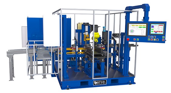
5-Station Turbine Damper Assembly Balancer
Fully-Automatic 5-Station Turbine Damper Assembly Balancer with Automatic Variable & Fixed Length Weight Making, Featuring Projection Weld Correction and Part Sorting
View More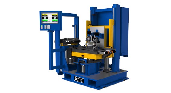
Fully-Automatic Brake Rotor Combination Bore & Multi-Attribute Gage
Fully-Automatic Brake Rotor Combination Bore & Multi-Attribute Gage Featuring Temperature Compensation and Auto Feedback to Upstream Machining Operations
View More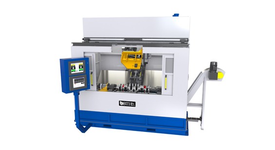
Crankshaft Balancer, Spindle Drill & Gantry Load
Fully-Automatic Crankshaft Balancer with High Pressure Coolant Through The Spindle Drill Correction and Overhead Gantry Load
View More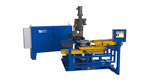
Fully-Automatic Heavy Duty Flywheel Balancer with Automatic Drill Correction and...
Fully-Automatic Heavy Duty Flywheel Balancer with Automatic Drill Correction and Load/Unload Assist Elevator
View More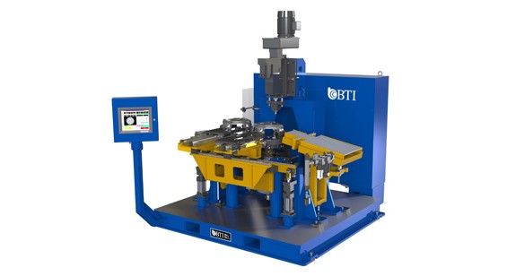
Fully-Automatic Large Clutch Housing Balancer with Automatic Drill Correction
Fully-Automatic Large Clutch Housing Balancer with Automatic Drill Correction
View More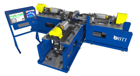
RDM Balancer & NVH Combination w/ Drill Correction
Fully-Automatic RDM Balancer & NVH Combination. Featuring Drill Correction, Laser Gaging, Drive Shaft Hung Mass Simulation and Advanced Clutch Conditioning Technology
View More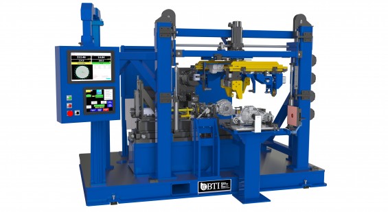
Fully-Automatic RDM Balancer Featuring Automatic Mill or Drill Correction
Fully-Automatic RDM Balancer Featuring Automatic Mill or Drill Correction, 180 Degree Rotary Load/Unload Station, Vision System to Detect Part Orientation, Part ID Scanner &...
View More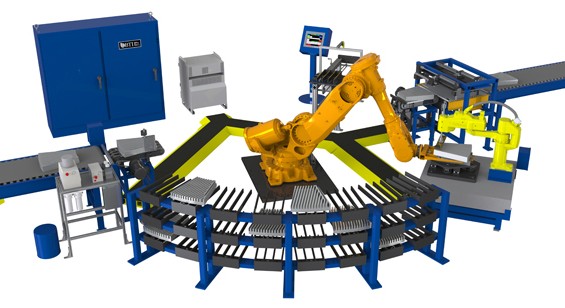
Fully-Automatic Refiner Plate Cell
Fully-Automatic Refiner Plate Cell Featuring Gaging and C.G. Measurement of Individual Plates for Predictive Balance Optimization when Assembled Per the Cell’s Advanced Sequencing and...
View More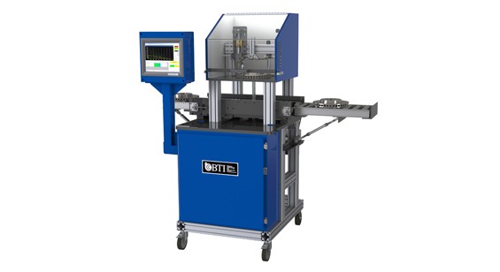
Fully-Automatic Resonant Frequency Measurement Station
Fully-Automatic Resonant Frequency Measurement Station
View More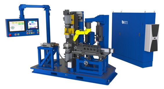
Single Station Torque Convertor Balancer
Fully-Automatic Single Station Torque Convertor Assembly Balancer with Automatic Variable and Fixed Length Weight Making and Weld Correction. Featuring Dual Motorized Spindles for Low...
View More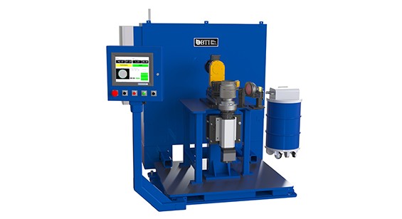
Transmission Clutch Housing Balancer, Drill Correction
Fully-Automatic Transmission Clutch Housing Balancer with Automatic Radial Drill Correction and Chip Containment System
View More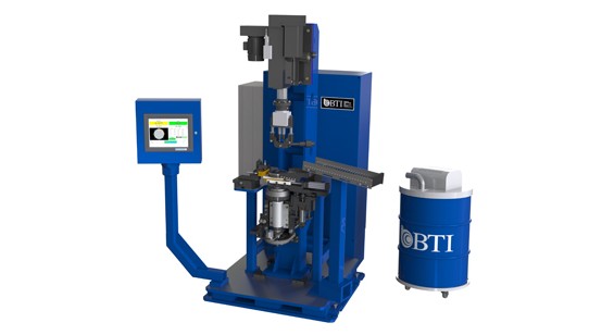
Harmonic Vibration Damper Balancer
Semi-Automatic Harmonic Vibration Damper Balancer with Automatic Servo Drill Correction, Featuring V-groove Dimensional Gaging, Auto Unload and Chip Containment
View More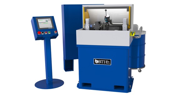
High Speed Assembly Balancer for Automotive Industry
Automatic High Speed Turbo Charger CHRA Core Assembly Balancer with Touch Up Grinder, Oil Pumping with Flow & Temperature Monitoring […]
View More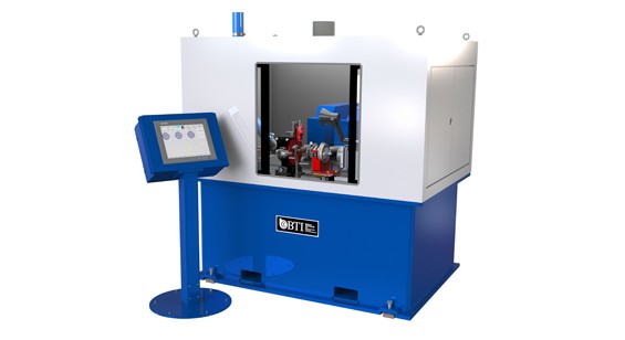
High Speed Turbo Charger Core Assembly 2 Plane Balancer
300,000 rpm High Speed Turbo Charger Core Assembly 2 Plane Balancer with Automatic Mill and Drill Correction, Featuring Pulsation Measurement, “G” Measurement, RPM sweep,...
View More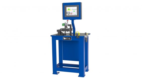
Horizontal Healthcare Fan / Blower Assembly Balancer
Horizontal Healthcare Fan / Blower Assembly Balancer with Programable Power Supply and Quick Connect Wire Harness.
View More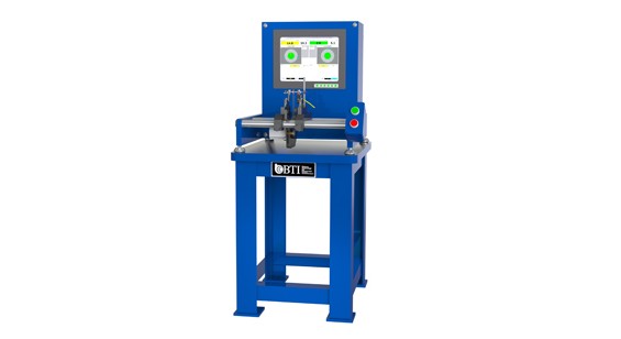
Horizontal Speedometer/Tachometer Needle Balancer
Horizontal Speedometer/Tachometer Needle Balancer
View More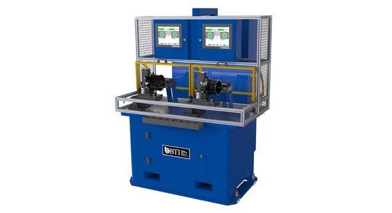
HVAC Fan Module Balancer and Motor Testing
Dual Station HVAC Fan Module Balancer Featuring Blade Counting, Motor Testing and Segmented Weight Correction
View More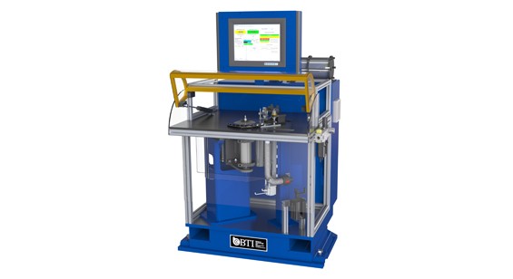
Impeller Balancer with Automatic Mill correction and Laser Gaging of Axial Run-O...
Impeller Balancer with Automatic Mill correction and Laser Gaging of Axial Run-Out
View More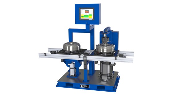
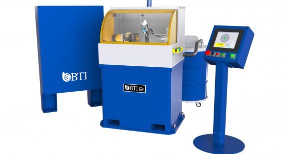
Low- and High-Speed Turbo Charger Core Assembly 2 Plane Balancer
4,000 to 300,000 rpm Low- and High-Speed Turbo Charger Core Assembly 2 Plane Balancer with Touch-Up Grinder, featuring Pulsation Measurement, “G” Measurement, and Oil...
View More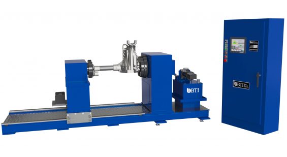
Manual Torsional Test Stand for Front Axle Assemblies.
Manual Torsional Test Stand for Front Axle Assemblies.
View More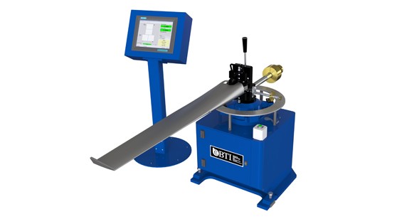
Moment Balancer for Helicopter Blades and Propellers
Moment Balancer for Helicopter Blades and Propellers
View More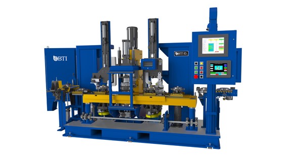
Multi-Station Combination Brake Rotor Machine
Fully Automatic Multi-Station Combination Brake Rotor Machine featuring Balancing with Mill Correction, Dimensional Gaging, Surface Finish Measurement, Eddy Current Crack Detection, and Part Marking
View More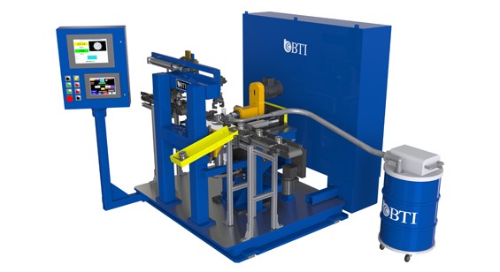
Multi-Station Flange Balancer with Correction Mill
Multi-Station Flange Balancer with Correction Mill
View More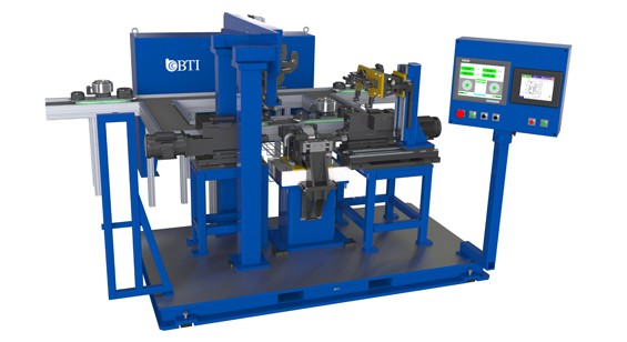
Multi-Station Magnetized Electric Armature Balancer
Fully Automatic Multi-Station Magnetized Electric Armature Balancer featuring Palletized Part Conveyance, Dual-Axial Drill Correction, and Heavy Spot Ink Marking
View More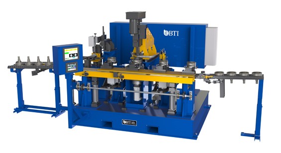
Multi-Station Transmission Carrier Combination Machine
Fully Automatic Multi-Station Transmission Carrier Combination Machine featuring Dimensional Gaging, Balancing with Automatic Drill Correction, Part Orientation Flipper, and Pin Stamp Marker
View More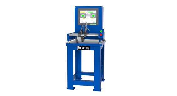
PC Cooling Fan Module Assembly Balancer with Motor Testing
PC Cooling Fan Module Assembly Balancer with Motor Testing
View More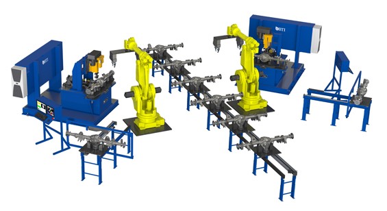
Rear Axle Cell featuring Two Drill Correction Balancers
Fully Automatic Rear Axle Cell featuring Two Drill Correction Balancers, Two Robots, Palletized Part Conveyance, Master Part Housing Stations, Part Marking, and RFID Traceability
View More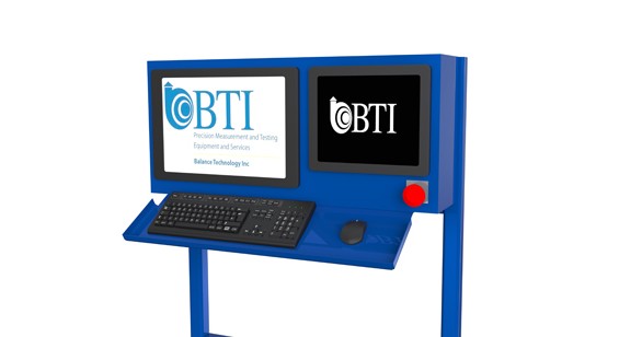
Replacement PC’s & PLC’s for all Brands and Models
Replacement PC’s & PLC’s for all Brands and Models
View More
Semi Automatic Two Station Turbine Wheel Mass Center and Audit Machine
Semi Automatic Two Station Turbine Wheel Mass Center and Audit Machine
View More
Semi-Automatic Armature Balancer, Drill Correction
Semi-Automatic Armature Balancer with Automatic Drill Correction and Automatic Servo-Controlled Commutator Lathe
View More
Semi-Automatic Clutch Housing Balancer with Automatic Drill Correction and Chip ...
Semi-Automatic Clutch Housing Balancer with Automatic Drill Correction and Chip Containment
View More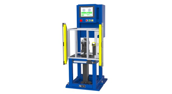
Semi-Automatic Compressor Wheel Air Bearing Audit Station
Semi-Automatic Compressor Wheel Air Bearing Audit Station Featuring Servo Controlled Whisper Drive Technology
View More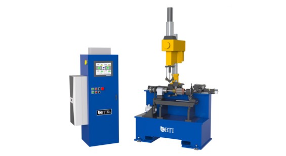
Semi-Automatic Crankshaft Balancer, Hook End Drive
Semi-Automatic Crankshaft Balancer Featuring Hook End Drive, Automatic Drill Correction, Paint Marker and Chip Containment System
View More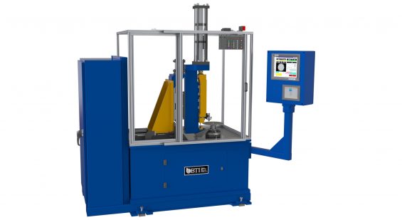
Semi-Automatic Drive Plate Balancer with Punch Correction and Slug Containment.
Semi-Automatic Drive Plate Balancer with Punch Correction and Slug Containment.
View More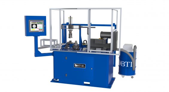
Semi-Automatic Flange Balancer with Mill Correction and Auto-Unload.
Semi-Automatic Flange Balancer with Mill Correction and Auto-Unload.
View More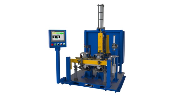
Semi-Automatic Flywheel Balancer
Semi-Automatic Flywheel Balancer with Automatic Pierce Correction, Slug Collection System, Pin Stamp Marking, Radial & Axial Dimensional Gaging
View More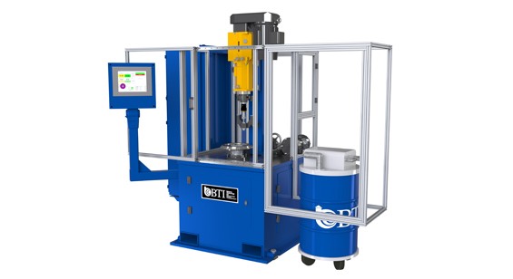
Semi-Automatic Flywheel Balancer with Automatic Drill Correction
Semi-Automatic Flywheel Balancer with Automatic Drill Correction
View More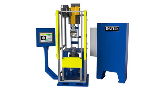
Semi-Automatic Harmonic Damper Balancer with Automatic Dual Drill Correction
Semi-Automatic Harmonic Damper Balancer with Automatic Dual Drill Correction and Vacuum Chip Removal
View More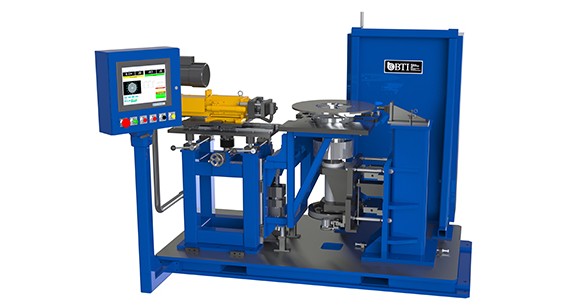
Semi-Automatic Heavy Duty Unvented Brake Rotor Balancer
Semi-Automatic Heavy Duty Unvented Brake Rotor Balancer with Automatic Radial Drill Correction and Load/Unload Assist Elevator
View More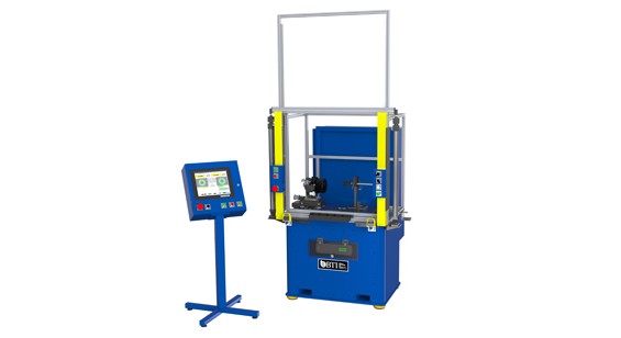
Semi-Automatic HVAC Fan Module Balancer
Semi-Automatic HVAC Fan Module Balancer Featuring Quick Disconnect Tooling for Multiple Part Models, Blade Counting, Motor Testing and Segmented Weight Correction
View More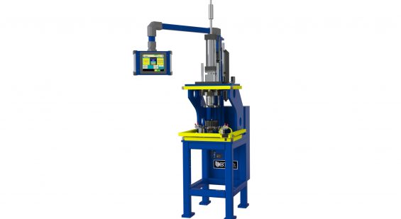
Semi-Automatic HVAC Fan Wheel / Motor Press Station. Capable of Pressing to both...
Semi-Automatic HVAC Fan Wheel / Motor Press Station. Capable of Pressing to both a Force and a Distance.
View More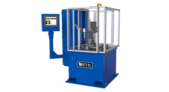
Semi-Automatic Reaction Carrier Balancer with Automatic Mill Correction and Part...
Semi-Automatic Reaction Carrier Balancer with Automatic Mill Correction and Part Marking
View More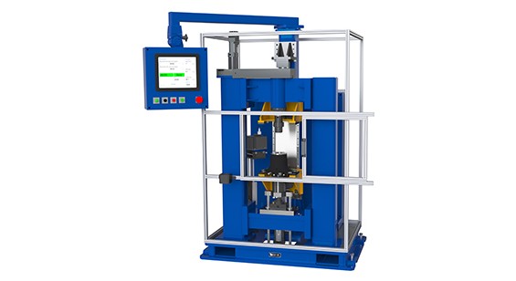
Semi-Automatic Rear Brake Hub Dynamic Axial Endplay and Bore Gage
Semi-Automatic Rear Brake Hub Dynamic Axial Endplay and Bore Gage
View More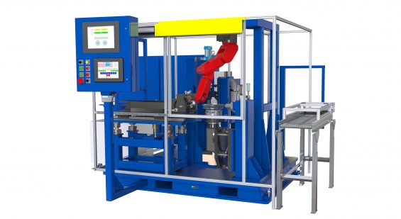
Semi-Auto Single Station Torsional Damper Balancer
Semi-Automatic Single Station Dynamic Torsional Damper Balancer with Automatic Projection Weld Correction
View More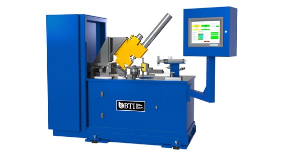
Semi-Automatic Torsional Machine Featuring
Semi-Automatic Torsional Damper Combination Machine Featuring Balancing with Automatic Pierce Correction, Dimensional Gaging, Part Marking, Rivet and Disallowed Area Sensing
View More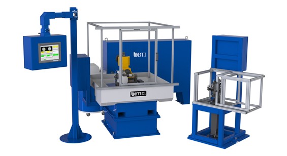
Semi-Automatic Turbo Charger Compressor Wheel Balance
Semi-Automatic Turbo Charger Compressor Wheel Balance Cell Featuring Air-Bearing Measurement Technology and Automatic Mill Correction
View More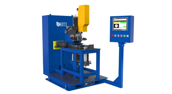
Semi-Automatic X-Ray Target Balancer
Semi-Automatic X-Ray Target Balancer with Automatic Servo Drill Correction Featuring Automatic Drill Changeover to Accommodate a Wide Varity of Parts without Operator Intervention
View More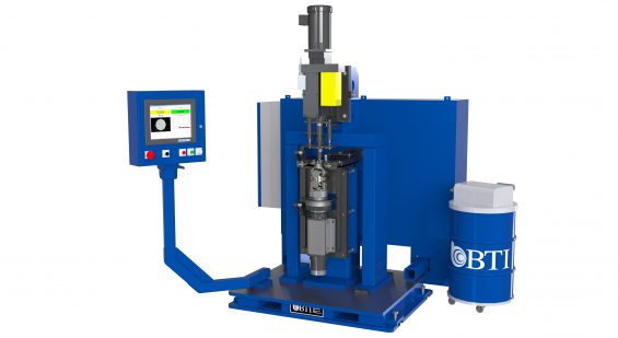
Semi-Automatic Yoke Assembly Balancer
Semi-Automatic Yoke Assembly Balancer with Drill Correction and Chip Containment
View More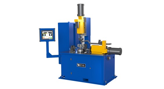
Snowmobile Clutch Balancer
Semi-Automatic Snowmobile Clutch Balancer with Automatic Axial & Radial Drill Correction
View More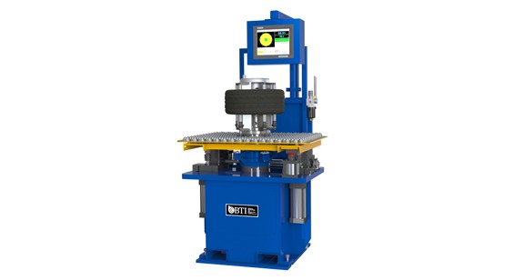
Static Aircraft Tire Balancer with Load Assist Elevator
Static Aircraft Tire Balancer with Load Assist Elevator
View More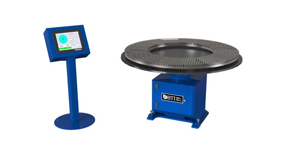
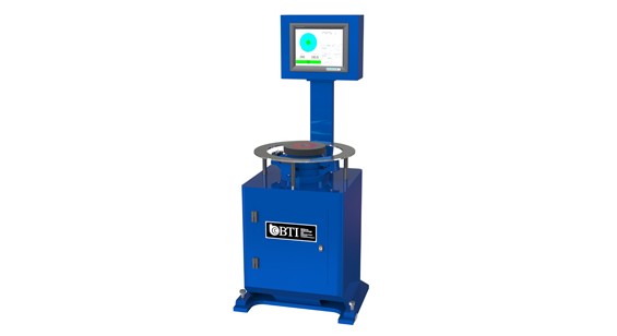
Static Grinding Wheel Audit Station with Pneumatic Tooling
Static Grinding Wheel Audit Station with Pneumatic Tooling
View More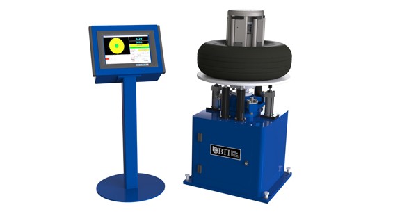
Static Tire Balancer with Pneumatic Paddle Style Tooling and Load Assist Elevato...
Static Tire Balancer with Pneumatic Paddle Style Tooling and Load Assist Elevator
View More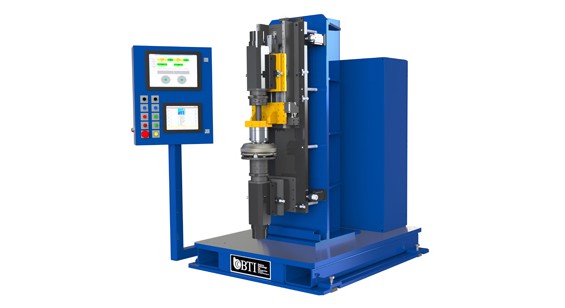
Torque Convertor Measure Station
Torque Convertor Measure Station Featuring Dual Motorized Spindles with Multiple Measurement Techniques (Static Internal, 180 Flip and Differential Measurement)
View More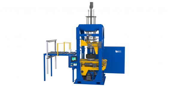
Truck Tire Inflator Balancer
Large Dynamic Truck Tire Inflator Balancer Featuring Radial & Lateral Laser Runout, Bead Lubrication, Load/Unload Elevator & Hot Stamp Unbalance Marking System.
View More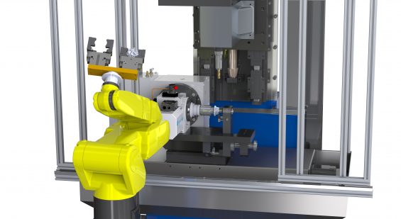
Turbo Charger Compressor Wheel Balancer
Fully Automatic Turbo Charger Compressor Wheel Balancer with 2-Plane BTI Mill Correction Station Featuring Robotic Part handling
View MoreGet Started
Get in touch with us. We're here to assist you.
Connect with our measurement experts and get the technical guidance your application demands.