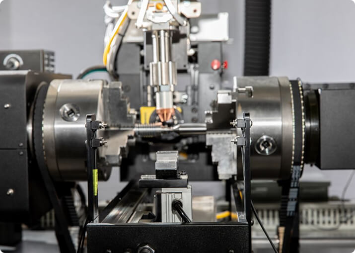

Electric Vehicle
BTI engineers and manufactures a complete line of manual, semi-automatic, and fully automatic precision measurement and testing equipment for all eDrive
View More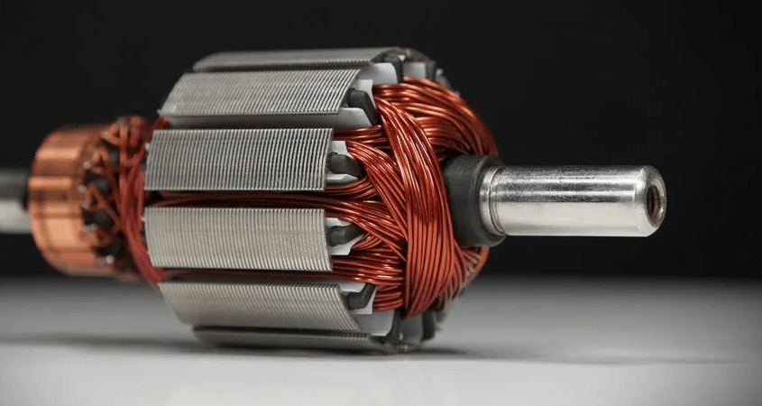
An electric machine rotor is a wound or magnet-bearing assembly, and its unbalance almost never comes from the machining. It comes from winding asymmetry, lamination stack variation, magnet placement, and the resin that holds all of it together. That changes where the problem is created and therefore where it has to be controlled.
Balance Technology Inc. builds manual, semi-automatic and fully automatic balancing, gauging and test equipment for armatures, wound rotors, induction rotors, permanent-magnet rotors and complete motor assemblies.
On a wound armature the dominant sources are the winding itself and the commutator. Coil placement varies within the slot, the amount of wire in each slot varies slightly, and the lead connections at the commutator are asymmetric by design. Lamination stacks add their own contribution through burr, stack height variation and slight bow.
On a permanent-magnet rotor the sources shift to magnet mass variation, magnet position within the pocket or on the surface, and the retaining sleeve or can. On an induction rotor, cast rotor bars and end rings carry porosity and fill variation.
The common thread is that all of these are assembly characteristics rather than machined features, which is why component-level dimensional control does not by itself produce a balanced rotor.
This is the sequencing mistake that costs the most. Varnish or resin impregnation adds mass, and it does not add it symmetrically — it wicks, pools and cures unevenly. A rotor balanced before impregnation will not be balanced after it.
The same logic applies to any downstream operation that adds or removes mass: sleeve fitting, banding, final machining of the shaft. Balance belongs after the last operation that changes mass distribution, not at the convenient point in the line.
Material removal from the lamination stack outside diameter or the end ring is the usual method where the design allows it, by milling or drilling. The constraint is electromagnetic as well as structural: removing iron from the stack changes the magnetic circuit, and removing material near the air gap changes it more.
Mass addition is common on wound armatures, using epoxy or balancing putty placed in the winding overhang or in designed pockets. It is fast and it avoids touching the magnetic path, but it depends on cure and adhesion, and an added weight that migrates in service is worse than the unbalance it corrected.
Permanent-magnet rotors frequently allow neither. Drilling near magnets risks demagnetization from heat and risks the retention system, so correction moves to designed balance rings or discs at the rotor ends.
Short armatures in low-speed appliance and power-tool duty are often single-plane parts. Traction and industrial rotors are not: they have real axial length, they run fast, and the couple they can develop matters. The decision follows from the diameter-to-length ratio and the service speed together.
Rotor tolerances follow ISO 21940-11 from a balance quality grade, the rotor mass and the service speed. Electric machines tend to sit at finer grades than their mechanical equivalents because the noise and vibration expectations are higher and there is no combustion event to mask anything. BTI publishes a free ISO 21940-11 balance tolerance calculator with the method behind it — grade selection, the permissible unbalance formula, plane allocation, and a worked example.
Most rotors are balanced on their own shaft, which makes shaft runout part of the measurement. A bent shaft or a damaged center produces a reading that no correction will resolve, because the rotor is not spinning about the axis the machine assumes.
Commutator runout is a separate characteristic with its own consequences — brush bounce, arcing and accelerated wear — and it is worth measuring alongside balance rather than inferring one from the other.
Motor lines commonly combine balancing with electrical test — resistance, surge and insulation — along with dimensional gauging of shaft and stack features, runout measurement, crack detection where the duty calls for it, and functional or NVH testing of the finished assembly. BTI builds equipment across that range, which matters where one station has to characterize a rotor several ways.
Layouts range from single manual stations through to fully automatic cells with correction, electrical test and data collection, and vary to accommodate any production rate. For platform selection across the full range, see BTI balancing machines.
Related applications include electric vehicle components, hard drives and head readers and HVAC assemblies.
Typical balance correction methods for motor assemblies include V-cut milling, contour milling, nibbling, UV and heat cure resigns, two-part epoxies, and clip addition
Additionally, BTI’s unique ability to combine the aforementioned technologies into one fully integrated system enables our clients to reduce capital expenditures, increase product quality, and minimize floor space requirements.
Let our staff of more than 50 engineers design a custom solution for your specific requirements. Furthermore, our commercial Measurement & Testing Services Group (M&T Services) can assist with everything from prototype testing and R&D work to master certification and running small-to-medium production runs.
If you don’t see the product you are looking for, or have specific questions, please contact us.
BTI engineers and manufactures a complete line of manual, semi-automatic, and fully automatic precision measurement and testing equipment for all eDrive
View More
BTI engineers and manufactures a complete line of manual, semi-automatic, and fully automatic precision measurement and testing equipment for all turbo charger components and complete assemblies
View More
BTI engineers and manufactures a complete line of manual, semi-automatic, and fully automatic precision measurement and testing equipment for turbines, jet engines, blades, propellers, steam turbines, and other related assemblies and components weighing fractions of an ounce to 200,000 pounds
View More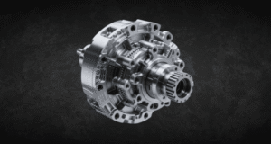
BTI engineers and manufactures a complete line of manual, semi-automatic, and fully automatic precision measurement and testing equipment for all types of transmission components
View More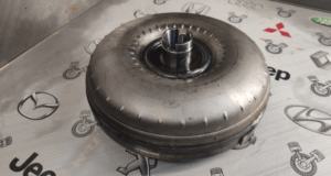
BTI engineers and manufactures a complete line of manual, semi-automatic, and fully automatic precision measurement and testing equipment for torque converters, turbines, dampers, stators, and all related assemblies and components
View More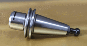
BTI engineers and manufactures both traditional spindled tool holder balancers and a patented (US Patent Numbers 5,763,777 and 5,965,815), first-of-its-kind, spindle-less balancer
View More
BTI engineers and manufactures a complete line of manual, semi-automatic, and fully automatic precision measurement and testing equipment for tire and tire/wheel assemblies for all wheel room applications
View More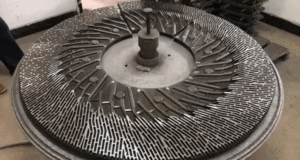
BTI engineers and manufactures a complete line of manual, semi-automatic, and fully automatic precision measurement and testing equipment for refiner plates
View More
BTI engineers and manufactures a complete line of manual, semi-automatic, and fully automatic precision measurement and testing equipment for pumps, fans, impellers, blowers, and related components
View More
BTI engineers and manufactures a complete line of manual, semi-automatic, and fully automatic precision measurement and testing equipment for all HVAC assemblies and related components
View More
BTI engineers and manufactures a complete line of manual, semi-automatic, and fully automatic precision measurement and testing equipment for hard drives, head readers, and related components
View More
BTI engineers and manufactures a complete line of manual, semi-automatic, and fully automatic precision measurement and testing equipment for all flywheels, flex plates, and related assemblies and components
View More
To contact us regarding your project - or if you have any questions - please click the button below :
Request a QuoteGet Started
Connect with our measurement experts and get the technical guidance your application demands.