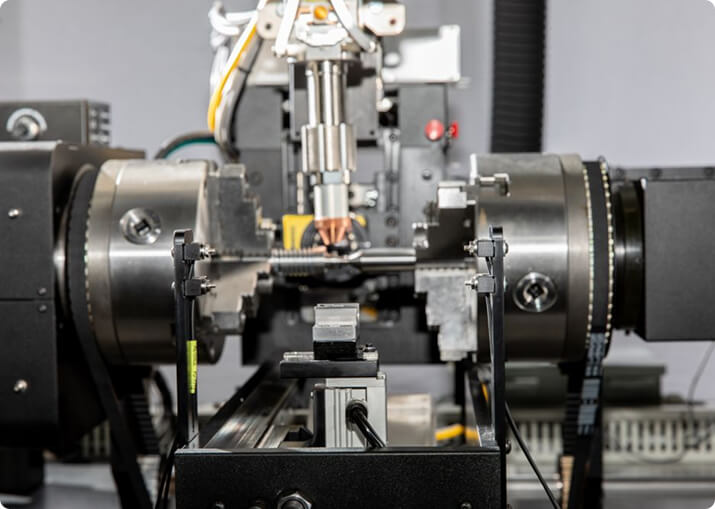

Electric Vehicle
BTI engineers and manufactures a complete line of manual, semi-automatic, and fully automatic precision measurement and testing equipment for all eDrive
View More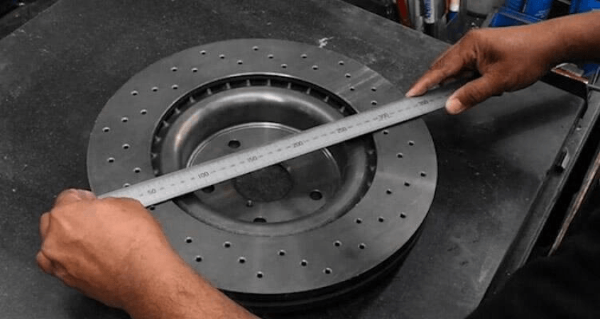
Brake rotor unbalance is real, it is measurable, and it is usually not what the customer is complaining about. The vibration a driver feels through the pedal and the steering wheel under braking is far more often disc thickness variation or lateral runout than residual unbalance. Any production strategy that treats balance as the whole answer will control the wrong variable.
Balance Technology Inc. builds balancing, dimensional gauging and crack detection equipment for brake rotors, drums, hubs and rotor-hub assemblies.
Disc thickness variation is the difference in thickness around the friction face. As the thick region passes under the pads it generates a brake torque variation once per revolution, felt as pedal pulsation. Meaningful DTV is measured in tens of microns, which is why it is a gauging problem rather than something you can see.
Lateral runout is wobble of the friction face relative to the axis. Its immediate effect is smaller than DTV’s, but it is the more dangerous of the two because it generates DTV over time: a rotor running out will contact the pads unevenly, wear unevenly, and develop thickness variation in service that was not there when it left the line.
Unbalance produces a rotating force that scales with the square of speed. It shows up as a shimmy at road speed rather than under braking, and on a wheel-end assembly it competes with tire and wheel unbalance that is usually larger.
All three matter. The point is that they are separate characteristics with separate causes, and a line that measures only one will pass parts that come back.
A solid or vented disc is a short, large-diameter rotor and is normally a single-plane part. Brake drums have more axial length and a different mass distribution, and the wider ones justify checking whether a couple is present rather than assuming it is not. Rotor-and-hub assemblies add bearing and hub mass at a different axial position and should be treated on their own merits.
The friction faces are functional surfaces with thickness, parallelism and finish specifications. Correction cannot come from them. Material is removed from the hat, the outer edge or the vent band, within limits set by section thickness and by the thermal duty the rotor has to survive.
Adhesive or clip weights are common in aftermarket and service practice but are generally unwelcome on an OEM part, because a weight that departs at temperature is worse than the unbalance it corrected.
Rotors are castings, and the unbalance is cast in. Core shift produces uneven wall thickness between the two friction faces of a vented rotor. Vane geometry varies. Porosity and hard carbide regions vary the density locally, and hard spots also cause uneven wear later, which brings you back to DTV.
Because the variation originates in the casting rather than the machining, dimensional control at the machine does not by itself produce a balanced rotor, and a badly out-of-family casting is often better rejected than corrected.
A rotor that is flat and parallel at room temperature can distort significantly at braking temperature, and it may or may not return. This is the reason a vehicle can develop judder after a period of service with no manufacturing defect present — thermal cycling, uneven pad deposition and corrosion all change the geometry that was correct at final inspection.
It also means that the acceptance limits set at manufacture should leave margin for the degradation the duty will impose, rather than passing parts that are marginal on day one.
Where a balance specification applies, it follows ISO 21940-11 from a balance quality grade, the rotor mass and the service speed. BTI publishes a free ISO 21940-11 balance tolerance calculator with the method behind it — grade selection, the permissible unbalance formula, plane allocation, and a worked example. DTV and runout limits come from the vehicle manufacturer rather than from the balancing standard.
Brake component lines normally combine balancing with:
On many lines the gauging station is the more consequential one.
Layouts range from single manual stations through to fully automatic cells combining gauging, balancing, correction and data collection, and vary to accommodate any production rate. For platform selection across the full range, see BTI balancing machines.
Related applications include tire and wheel assemblies, axles and RDU components and flanges and yokes.
How are brake rotors balanced?
Most production brake rotors are balanced in a single plane, since the rotor is a disc whose diameter far exceeds its thickness. Correction is made by removing material from the hat or the outer edge, or by machining the friction faces. High-volume lines balance and correct in one automated cycle.
Why do brake rotors need balancing at all?
An unbalanced rotor is rotating mass on the wheel end, where it acts directly on the suspension and steering. The result is a speed-dependent vibration felt through the steering wheel that drivers report as a fault regardless of braking performance. The rotor also carries the wheel, so its unbalance adds to whatever the tire and wheel assembly already contribute.
Is brake rotor vibration caused by unbalance or by thickness variation?
Usually thickness variation, not unbalance. Disc thickness variation produces a pulsation felt through the brake pedal when braking; unbalance produces a vibration felt at speed whether or not the brakes are applied. The two are different faults with different causes, and telling them apart is the first step in diagnosing a complaint.
Can brake rotors be balanced after machining?
Yes, and resurfacing a rotor changes its balance, so the order matters. If material is removed unevenly across the friction faces — which is what resurfacing a warped rotor does — the rotor’s mass distribution changes. Balancing should follow final machining, not precede it.
What else is measured on a brake rotor besides balance?
Thickness variation, lateral runout, flatness and parallelism of the friction faces, surface finish, and often crack detection. Several of these can be measured in the same cycle as balancing when the rotor is already spinning on a precise axis.
Do drums and rotors have the same balancing requirements?
The principle is the same but the geometry differs. A drum has a greater axial length relative to its diameter, so couple unbalance matters more and two-plane balancing is sometimes required where a rotor would be corrected in one.
Our standard offerings include patented combinations of balancing, gaging, surface finish measurement, and crack detection “” all in one machine. In addition, we specialize in standalone single technology equipment.
Typical correction methods for balancing include milling, weight addition by welding, and weight insertion. Cycle times range from 60 to 300 parts per hour.
Additionally, BTI’s unique ability to combine the aforementioned technologies into one fully integrated system enables our clients to reduce capital expenditures, increase product quality, and minimize floor space requirements.
Let our staff of more than 50 engineers design a configured-to-order solution for your specific requirements. Furthermore, our commercial Measurement & Testing Services Group (M&T Services) can assist with everything from prototype testing and R&D work to master certification and running small-to-medium production runs.
If you don’t see the product you are looking for, or have specific questions, please contact us.
BTI engineers and manufactures a complete line of manual, semi-automatic, and fully automatic precision measurement and testing equipment for all eDrive
View More
BTI engineers and manufactures a complete line of manual, semi-automatic, and fully automatic precision measurement and testing equipment for all turbo charger components and complete assemblies
View More
BTI engineers and manufactures a complete line of manual, semi-automatic, and fully automatic precision measurement and testing equipment for turbines, jet engines, blades, propellers, steam turbines, and other related assemblies and components weighing fractions of an ounce to 200,000 pounds
View More
BTI engineers and manufactures a complete line of manual, semi-automatic, and fully automatic precision measurement and testing equipment for all types of transmission components
View More
BTI engineers and manufactures a complete line of manual, semi-automatic, and fully automatic precision measurement and testing equipment for torque converters, turbines, dampers, stators, and all related assemblies and components
View More
BTI engineers and manufactures both traditional spindled tool holder balancers and a patented (US Patent Numbers 5,763,777 and 5,965,815), first-of-its-kind, spindle-less balancer
View More
BTI engineers and manufactures a complete line of manual, semi-automatic, and fully automatic precision measurement and testing equipment for tire and tire/wheel assemblies for all wheel room applications
View More
BTI engineers and manufactures a complete line of manual, semi-automatic, and fully automatic precision measurement and testing equipment for refiner plates
View More
BTI engineers and manufactures a complete line of manual, semi-automatic, and fully automatic precision measurement and testing equipment for pumps, fans, impellers, blowers, and related components
View More
BTI engineers and manufactures a complete line of manual, semi-automatic, and fully automatic precision measurement and testing equipment for all HVAC assemblies and related components
View More
BTI engineers and manufactures a complete line of manual, semi-automatic, and fully automatic precision measurement and testing equipment for hard drives, head readers, and related components
View More
BTI engineers and manufactures a complete line of manual, semi-automatic, and fully automatic precision measurement and testing equipment for all flywheels, flex plates, and related assemblies and components
View More
To contact us regarding your project - or if you have any questions - please click the button below :
Request a QuoteGet Started
Connect with our measurement experts and get the technical guidance your application demands.