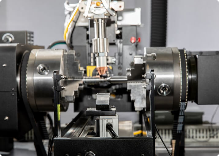

Electric Vehicle
BTI engineers and manufactures a complete line of manual, semi-automatic, and fully automatic precision measurement and testing equipment for all eDrive
View More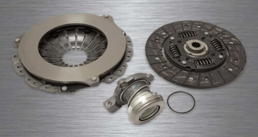
A clutch is not a rigid rotor, and that one fact drives everything about how it has to be balanced. A crankshaft or an armature carries its mass in fixed relation to its axis. A centrifugal clutch does not: flyweights swing, sheaves translate along the shaft, rollers ride up ramps, and springs load and unload. The mass distribution you measure at rest is not the distribution the assembly runs with at engagement speed.
Balance Technology Inc. builds manual, semi-automatic and fully automatic balancing, gauging and test equipment for clutch assemblies and the components that go into them — snowmobile and off-road CVT primary and secondary clutches, motorcycle and ATV centrifugal clutches, torque converter clutch assemblies, and the sheaves, hubs, covers, spiders and flyweight carriers built into them.
Three characteristics separate a clutch from an ordinary production rotor, and each one changes how the machine and the tooling have to be designed.
Both approaches are legitimate and they answer different questions. Balancing individual components — the fixed sheave, the movable sheave, the cover — controls the inputs and catches castings and machined parts that are out of family before value is added to them. Balancing the completed assembly controls what the customer actually receives, including stack-up from fasteners, flyweights and the relative angular position of each part.
High-volume production usually does both: component balancing as a gate, assembly balancing as the final acceptance. Lower-volume and aftermarket work more often balances the assembly alone. The right answer depends on where the variation is coming from, which is a measurement question before it is an equipment question.
Continuously variable transmission clutches are the demanding case. The primary or drive clutch carries flyweights, a movable sheave and a spring, and it mounts on a crankshaft taper — so the balance condition that matters is the one it presents when assembled to that taper, not the one it shows on an arbitrary mandrel. The secondary or driven clutch adds a helix and a torsion spring, and its mass distribution changes with the angular position of the movable sheave.
BTI builds dedicated equipment for this work, including a semi-automatic snowmobile clutch balancer with automatic axial and radial drill correction. The same platform approach applies to ATV, side-by-side and utility vehicle clutch families.
Two correction directions are available on most clutch geometry, and production machines often need both. Axial drilling removes material parallel to the axis, into a face or a boss, and suits assemblies where the rim must stay intact. Radial drilling removes material perpendicular to the axis, into the outer diameter, and gives more correction per unit of depth because the radius arm is longer.
Which one a part can accept is set by wall thickness, proximity to the belt surface, structural requirements and appearance. Machines built for clutch work carry correction limits in the control so an out-of-family part is rejected rather than drilled past what the design allows.
Clutch balance tolerances are normally specified against ISO 21940-11, using a balance quality grade, the assembly mass and the service speed. The grade selection is an engineering judgment; the arithmetic that follows it is not. BTI publishes a free ISO 21940-11 balance tolerance calculator along with the method behind it — grade selection, the permissible unbalance formula, allocation across two planes, and a worked example.
One caution specific to clutches: a tolerance stated for the assembly does not divide cleanly into tolerances for its components, because the components combine vectorially and can cancel or compound depending on assembly orientation.
More clutch balancing arguments are caused by tooling than by machines. The fixture has to locate on the same feature the part will run on — typically the taper bore or the shaft journal — and it has to repeat that location every cycle. Any fixture carries unbalance of its own, and that unbalance adds to the part vectorially.
The check that settles it is an index test: measure the part as mounted, rotate it 180 degrees relative to the tooling, re-clamp and measure again. Half the vector difference between the two readings is the part; half the vector sum is the tooling. It takes one extra spin and it separates a fixture problem from a part problem before anyone starts adjusting a machine.
Clutch production lines rarely measure unbalance alone. Depending on the component and the failure modes being controlled, BTI equipment for this application also covers:
Traditional equipment for this application includes:
Layouts range from single manual stations through fully automatic cells, and vary to accommodate any production rate.
Related applications include torque converters and components and transmission components. For platform selection across the full range, see BTI balancing machines.
How are clutch assemblies balanced?
A clutch assembly is balanced as a complete unit — cover, pressure plate, diaphragm spring and any damper — on the pilot and the flywheel mounting face, so it is measured about the axis it will actually turn on. Correction is normally by adding rivets or weights to the cover, or by removing material from designated areas.
Should the clutch be balanced separately or with the flywheel?
Both approaches are used. Balancing the clutch alone is normal in production because the clutch and flywheel are built in different places. Balancing them together as a matched assembly gives a better result and is common in performance and heavy duty applications, but it commits the two parts to each other and they must then be marked and reassembled in the same orientation.
Why do clutches go out of balance?
Because they are assemblies of stamped and formed parts joined by rivets and welds. The cover is a stamping, the diaphragm spring is not perfectly uniform, damper springs vary in mass, and riveting introduces asymmetry. Each contribution is small; together they matter at engine speed.
What happens if a clutch assembly is out of balance?
Vibration transmitted into the crankshaft and the transmission input shaft, felt as a speed-dependent shake that changes when the clutch is disengaged. Because the clutch hangs off the end of the crankshaft, its unbalance also loads the rear main bearing and the crankshaft thrust face.
Does the clutch disc need balancing too?
Usually yes, and it is balanced separately because it rotates independently of the cover when the clutch is disengaged. The disc carries the hub, damper springs and friction material, all of which vary. In most production processes the disc and the cover assembly each have their own tolerance.
Can a clutch be rebalanced after resurfacing?
Yes, and it should be. Resurfacing a pressure plate removes material from the friction face, which changes mass distribution. Any clutch component that has been machined needs to be rebalanced before it returns to service.
Typical correction methods for balancing include drilling, milling, piercing, projection and spot welding with automatic weight feed, form, and place.
Additionally, BTI’s unique ability to combine the aforementioned technologies into one fully integrated system enables our clients to reduce capital expenditures, increase product quality, and minimize floor space requirements.
Let our staff of more than 50 engineers design a configured-to-order solution for your specific requirements. Furthermore, our commercial Measurement & Testing Services Group (M&T Services) can assist with everything from prototype testing and R&D work to master certification and running small-to-medium production runs.
If you don’t see the product you are looking for, or have specific questions, please contact us.
BTI engineers and manufactures a complete line of manual, semi-automatic, and fully automatic precision measurement and testing equipment for all eDrive
View More
BTI engineers and manufactures a complete line of manual, semi-automatic, and fully automatic precision measurement and testing equipment for all turbo charger components and complete assemblies
View More
BTI engineers and manufactures a complete line of manual, semi-automatic, and fully automatic precision measurement and testing equipment for turbines, jet engines, blades, propellers, steam turbines, and other related assemblies and components weighing fractions of an ounce to 200,000 pounds
View More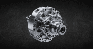
BTI engineers and manufactures a complete line of manual, semi-automatic, and fully automatic precision measurement and testing equipment for all types of transmission components
View More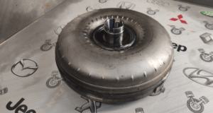
BTI engineers and manufactures a complete line of manual, semi-automatic, and fully automatic precision measurement and testing equipment for torque converters, turbines, dampers, stators, and all related assemblies and components
View More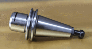
BTI engineers and manufactures both traditional spindled tool holder balancers and a patented (US Patent Numbers 5,763,777 and 5,965,815), first-of-its-kind, spindle-less balancer
View More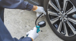
BTI engineers and manufactures a complete line of manual, semi-automatic, and fully automatic precision measurement and testing equipment for tire and tire/wheel assemblies for all wheel room applications
View More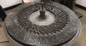
BTI engineers and manufactures a complete line of manual, semi-automatic, and fully automatic precision measurement and testing equipment for refiner plates
View More
BTI engineers and manufactures a complete line of manual, semi-automatic, and fully automatic precision measurement and testing equipment for pumps, fans, impellers, blowers, and related components
View More
BTI engineers and manufactures a complete line of manual, semi-automatic, and fully automatic precision measurement and testing equipment for all HVAC assemblies and related components
View More
BTI engineers and manufactures a complete line of manual, semi-automatic, and fully automatic precision measurement and testing equipment for hard drives, head readers, and related components
View More
BTI engineers and manufactures a complete line of manual, semi-automatic, and fully automatic precision measurement and testing equipment for all flywheels, flex plates, and related assemblies and components
View More
To contact us regarding your project - or if you have any questions - please click the button below :
Request a QuoteGet Started
Connect with our measurement experts and get the technical guidance your application demands.