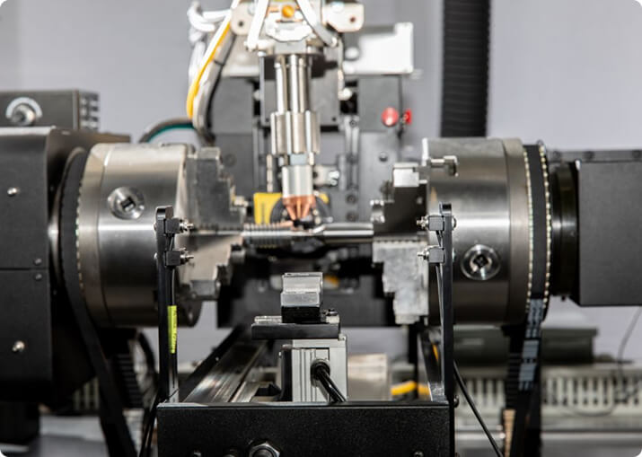

Electric Vehicle
BTI engineers and manufactures a complete line of manual, semi-automatic, and fully automatic precision measurement and testing equipment for all eDrive
View More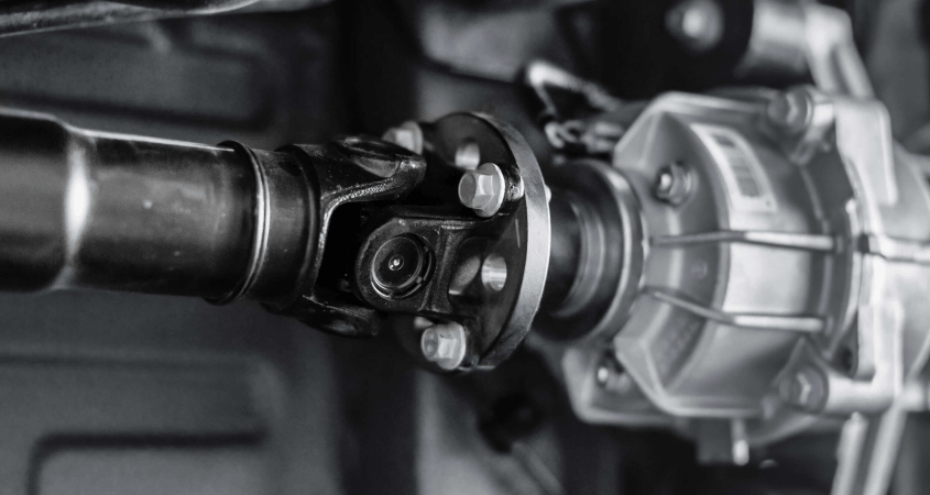
A driveshaft is a long, slender rotor, and that single geometric fact separates it from almost everything else on a balancing floor. Its first bending critical speed can sit close to or below its service speed, which means it does not behave as a rigid body when it matters. Balance it at 300 rpm and it may still vibrate at 3,000.
Balance Technology Inc. builds manual, semi-automatic and fully automatic balancing and measurement equipment for one-piece and two-piece driveshafts in steel and aluminum, including automatic weld correction, and for the yokes, flanges and slip assemblies that go into them.
ISO 21940 treats rigid and flexible rotors differently for good reason. A rigid rotor keeps the same mass distribution at every speed, so two correction planes fully describe it and a low-speed balance is valid at service speed. A flexible rotor bows, and the bow itself creates unbalance that only appears as speed rises.
Whether a given shaft is rigid in service is a calculation from its length, diameter, wall thickness and operating speed — not a judgment to make by eye. Short, large-diameter shafts are usually safely rigid. Long, thin, high-speed shafts frequently are not, and those need either balancing near service speed or a design change that raises the critical speed above the operating range.
A two-piece shaft with a center support bearing is not two independent rotors. The center bearing constrains the shaft, changes its mode shapes, and couples the two sections. Balancing each half separately and assembling them does not reliably give a balanced assembly, and the correction planes that matter are not always the ones at the tube ends.
Production practice is normally to balance the assembly as it will run, with the center bearing carried in tooling that reproduces its service mounting stiffness. Tooling that holds the bearing more rigidly than the vehicle does will give a reading the vehicle does not reproduce.
Driveshafts are corrected by adding mass, not removing it. The tube wall is thin and structural, so drilling is not available. The standard production method is resistance welding a correction weight to the tube at the required angular position and axial plane.
That constrains the process in ways worth designing around. Correction resolution is set by the discrete weight sizes available, so the process needs a weight range fine enough to hit the tolerance without an unreasonable number of pieces. Weld position repeatability directly becomes balance repeatability. And the weld itself must not compromise the tube — heat input, electrode condition and surface preparation are balance-quality variables, not just weld-quality variables.
Aluminium shafts change the method again, since resistance welding steel weights to aluminum is not available and the correction approach has to suit the substrate.
Balance and runout are different measurements and they are routinely confused. A shaft can be balanced to tolerance and still run out badly, and runout produces vibration that no amount of balancing will remove.
Tube straightness, weld-seam quality at the yoke joints, and the concentricity of the yokes to the tube axis all contribute. A production line that measures balance without measuring runout will pass parts that come back as warranty claims. Universal joints and slip yokes add their own contribution, and a joint with excessive lash will not give a repeatable reading at all.
Driveshaft tolerances are specified against ISO 21940-11 from a balance quality grade, the shaft mass and its maximum service speed. BTI publishes a free ISO 21940-11 balance tolerance calculator alongside the method — grade selection, the permissible unbalance formula, allocation across planes, and a worked example.
One caution specific to long shafts: a tolerance derived on the assumption of rigid behavior is not valid if the shaft is flexible at service speed. Confirm the rigid-rotor assumption before relying on the arithmetic.
Whatever holds the shaft carries unbalance of its own, and on a light tube that contribution is proportionally large. The drive end matters too — belt drive, end drive and universal-joint drive each impose their own contribution, and a drive component with runout adds to the reading in a way that is easy to blame on the part.
An index test separates the two. Measure as mounted, rotate the shaft 180 degrees relative to the tooling, re-clamp and measure again. Half the vector difference is the part; half the vector sum is the tooling.
Driveshaft lines commonly combine balancing with:
Equipment for this application also includes crack detection where the failure modes call for it.
Layouts range from single manual stations through to a fully automatic driveshaft balancing machine with automatic weld correction, guarding, excessive-vibration shutoff and dual servo drives, and vary to accommodate any production rate. For platform selection across the full range, see BTI balancing machines.
Related applications include flanges and yokes, axles and RDU components and transmission components.
How are driveshafts balanced?
A driveshaft is balanced as an assembly on its own journals or centering surfaces, spun at or near its service speed range, with unbalance measured in two planes. Correction is normally made by welding or bonding balance weights to the tube, since material cannot be removed from a thin-wall tube without compromising it. Two-plane correction is required because a driveshaft is a long rotor and couple unbalance dominates.
Why do driveshafts need two-plane balancing instead of one?
Balance behavior depends on the ratio of length to diameter. A driveshaft is long relative to its diameter, so unbalance at one end and unbalance at the other create a couple — a rocking moment that single-plane correction cannot remove. Correcting only one plane can leave the shaft worse than before. Anything longer than roughly twice its diameter should be treated as a two-plane problem.
What balance tolerance should a driveshaft have?
The tolerance comes from the balance quality grade in the part specification, the mass of the shaft, and its maximum service speed. Automotive driveshafts commonly sit in the G 16 to G 40 range, but the number that matters is the one on your print. Our ISO 21940-11 calculator converts a grade and service speed into a permissible residual unbalance.
Can a driveshaft be balanced with the universal joints attached?
Yes, and for most applications it should be. The joints and slip yoke contribute unbalance of their own, and balancing the bare tube leaves that contribution uncorrected. Balancing the complete assembly in its service configuration is what produces a shaft that runs smoothly in the vehicle.
Why does a driveshaft that passed balancing still vibrate in service?
Most often because the unbalance was corrected but the runout was not, or because the assembly is being indexed differently in the vehicle than it was on the balancer. Bent tube, worn joints, misaligned flanges and incorrect phasing between joints all produce vibration that balancing cannot fix. A driveshaft that reads good on the machine and bad in the car usually has a geometry problem, not an unbalance problem.
What speed should a driveshaft be balanced at?
At or close to the speed range it will see in service, because a long shaft’s response changes with speed. Balancing well below service speed can miss behavior that only appears as the shaft approaches its first critical speed. Where the service range crosses a critical, the shaft has to be treated as flexible rather than rigid.
Every machine below was designed, built and commissioned by BTI for driveshaft work. Each page carries the configuration, correction method and handling detail for that build.
Typical correction methods include manual weight addition, automatic projection, and spot welding of preformed or machine-made weights.
Additionally, BTI’s unique ability to combine the aforementioned technologies into one fully integrated system enables our clients to reduce capital expenditures, increase product quality, and minimize floor space requirements.
Let our staff of more than 50 engineers design a configured-to-order solution for your specific requirements. Furthermore, our commercial Measurement & Testing Services Group (M&T Services) can assist with everything from prototype testing and R&D work to master certification and running small-to-medium production runs.
If you don’t see the product you are looking for, or have specific questions, please contact us.
BTI engineers and manufactures a complete line of manual, semi-automatic, and fully automatic precision measurement and testing equipment for all eDrive
View More
BTI engineers and manufactures a complete line of manual, semi-automatic, and fully automatic precision measurement and testing equipment for all turbo charger components and complete assemblies
View More
BTI engineers and manufactures a complete line of manual, semi-automatic, and fully automatic precision measurement and testing equipment for turbines, jet engines, blades, propellers, steam turbines, and other related assemblies and components weighing fractions of an ounce to 200,000 pounds
View More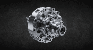
BTI engineers and manufactures a complete line of manual, semi-automatic, and fully automatic precision measurement and testing equipment for all types of transmission components
View More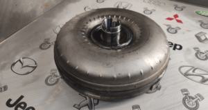
BTI engineers and manufactures a complete line of manual, semi-automatic, and fully automatic precision measurement and testing equipment for torque converters, turbines, dampers, stators, and all related assemblies and components
View More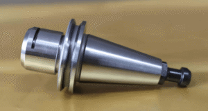
BTI engineers and manufactures both traditional spindled tool holder balancers and a patented (US Patent Numbers 5,763,777 and 5,965,815), first-of-its-kind, spindle-less balancer
View More
BTI engineers and manufactures a complete line of manual, semi-automatic, and fully automatic precision measurement and testing equipment for tire and tire/wheel assemblies for all wheel room applications
View More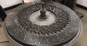
BTI engineers and manufactures a complete line of manual, semi-automatic, and fully automatic precision measurement and testing equipment for refiner plates
View More
BTI engineers and manufactures a complete line of manual, semi-automatic, and fully automatic precision measurement and testing equipment for pumps, fans, impellers, blowers, and related components
View More
BTI engineers and manufactures a complete line of manual, semi-automatic, and fully automatic precision measurement and testing equipment for all HVAC assemblies and related components
View More
BTI engineers and manufactures a complete line of manual, semi-automatic, and fully automatic precision measurement and testing equipment for hard drives, head readers, and related components
View More
BTI engineers and manufactures a complete line of manual, semi-automatic, and fully automatic precision measurement and testing equipment for all flywheels, flex plates, and related assemblies and components
View More
To contact us regarding your project - or if you have any questions - please click the button below :
Request a QuoteGet Started
Connect with our measurement experts and get the technical guidance your application demands.