
Electric Vehicle
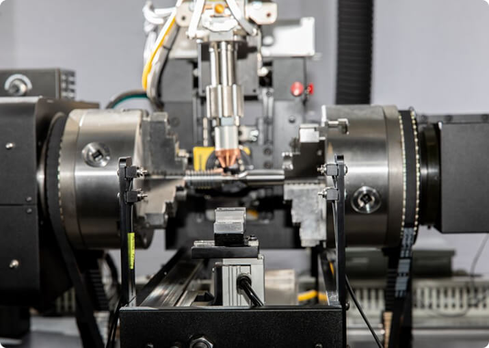
BTI engineers and manufactures a complete line of manual, semi-automatic, and fully automatic precision measurement and testing equipment for all eDrive
View More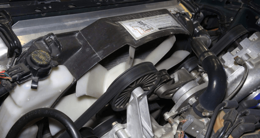
An engine cooling fan module is one of the harder assemblies in a vehicle to balance well, and the reason is structural rather than procedural: the module is its own spindle and bearing system. You are not mounting a rigid rotor on a known, stiff machine spindle — you are measuring an assembly that brings its own shaft, its own bearings, its own clearances, and its own flexible blades to the measurement.
Balance Technology Inc. builds manual, semi-automatic, and fully automatic measurement and testing equipment for engine cooling fan modules, fan-and-motor assemblies, and related rotating components, for both OEM production lines and tier-supplier plants.
Fan module readings are influenced by fan and rotor dynamics in ways that a plain rigid-rotor balancing machine cannot separate out:
The practical consequence is that a fan module does not have one true unbalance value. It has a speed-dependent behavior, and the job of the equipment is to measure that behavior repeatably at the speed that matters for your application — not to pretend the assembly is a rigid rotor.
BTI typically measures engine cooling fan modules on a horizontal suspension platform system fitted with a wind shroud. The platform carries the assembly on two factory-calibrated, hard-bearing piezo-ceramic work supports, with the part located and clamped by tooling built to its specific geometry. The wind shroud directly addresses the air buffeting problem — it manages the airflow the fan is generating so that what reaches the transducers is the assembly’s dynamic signature rather than the turbulence it is stirring up.
Machine designations name the platform and its class, for example a P-5: P for the platform suspension base, 5 for the machine class. Class sets the size and load envelope of the base, and platform suspension bases are offered across a range of classes; control type, correction method, drive and shroud are then specified around the part. (Older quotations may show this base as an SH-5, a designation BTI has since retired.)
The figures below describe a typical P-5 class semi-automatic fan module measuring machine with operator load and unload. Every BTI machine is configured to your part, so these are a starting point rather than a fixed specification.
| Measurement type | Dynamic two-plane unbalance measurement |
|---|---|
| Part weight range, nominal | 0.1 lb – 10 lb (class dependent) |
| Balancing speed | 300 to 3,600 rpm, variable |
| Drive | Brushless AC servo, dynamic braking |
| Measurement time | Approximately 20 seconds per measurement |
| Work supports | Two hard-bearing, factory-calibrated piezo-ceramic supports |
| Controls | Industrial PLC with touchscreen, 24 VDC, Ethernet to the measurement system |
| Footprint | Approximately 38 in. x 40 in. |
| Power | 230 VAC / 1 phase / 60 Hz |
| Guarding | Extruded aluminum frame with Lexan or coated wire mesh, electrically interlocked access door |
Larger fans move up the class range. BTI has built static balancers for fans in the 1,000 lb class and fully automatic systems with rivet, mill, and weight-add correction where production volume justifies them.
Fan module machines run BTI’s BalCORE measurement system on an industrial PC with a NEMA-rated 19 in. touch panel. Because fan work is dynamics-sensitive, the data side matters as much as the mechanics.
Unbalance can be displayed as force (static), force/couple, or two-plane, in English or metric units — oz-in, g-mm, g-cm, g-m, kg-mm, kg-cm, kg-m, g-in, N-m, or as unbalance at a selected correction radius. Operators set tolerance levels for acceptable and reject parts, decimal places, and whether correction is by adding or removing weight, and can store part setups in machine memory for changeover.
Built-in statistical functions cover the studies a fan program is normally qualified against:
Incoming unbalance, outgoing unbalance, part parameters, part number, date, and time can be written to the machine’s drive and exported over USB or Ethernet. Real-time analog and digital signal plots are available on-screen, which is often what you need when diagnosing a fan that behaves differently at two speeds.
Engine cooling module lines rarely stop at balancing. BTI builds these checks into cooling fan stations, individually or combined:
Station layouts and automation levels are set by your production rate — single-station semi-automatic through multi-station automatic, including press stations that press a fan wheel to both a force and a distance.
Every fan module machine ships with production balance masters: a customer part modified with a hardened and ground insert and precision holes for placement of certified test weights, supplied in a fitted storage box with certifications. Calibration is performed at the BTI factory and can be verified or redone at any time against that master, and the system stores multiple part-specific calibrations.
Runoff is done with real parts. BTI asks for a minimum of ten parts of each type ahead of shipment so BTI can debug and try out the machine under simulated production conditions, verifying safety, quality, and production rate before it leaves Whitmore Lake.
Because a fan module’s behavior is set by its own dynamics, the honest answer to “what capability will this machine hold?” depends on the part, not only on the equipment. Two assemblies with the same nominal drawing can behave differently if their bearings, blade stiffness, or clearances differ.
That is why BTI’s Measurement & Testing Division (M&T Services) exists. Sending BTI parts for evaluation and testing — or sending existing data that accurately represents the product — lets acceptance criteria be established against how your fan actually behaves, with any adverse characteristics identified before the machine is designed rather than discovered at runoff.
If you can share the fan module, its operating speed range, and the throughput you need, a BTI application engineer can tell you what platform class, tooling, shroud, and station layout the job calls for — and whether part evaluation should come first.
Contact BTI to start an engine cooling fan balancing discussion.
The rotating element — the fan, and on some designs the water pump impeller and viscous clutch assembly. The module as a whole is not balanced; its rotating components are, individually or as sub-assemblies, before the module is built.
Because they are large-diameter, low-mass rotating parts turning close to the passenger compartment, and unbalance in them produces noise and vibration the driver hears directly. Molded plastic fans also vary from shot to shot, so each one is a slightly different rotor.
Generally yes. Injection molding produces wall thickness and density variation that dimensional inspection does not catch, and the blades are thin enough that small variations matter. A molded fan can be within every dimension on the print and still be out of balance.
By adding weight rather than removing it, since there is little material to spare and cutting a thin blade weakens it. Most designs include bosses or pockets on the hub or blade roots specifically for balance weights, sized and placed during the design of the part.
No. Fan noise is dominated by aerodynamics — blade passing frequency, tip clearance, inlet distortion from the shroud and radiator — none of which balancing affects. Balancing removes the once-per-revolution excitation and nothing else, which is why cooling modules are usually tested for noise as well.
Typical balance correction methods for engine cooling module assemblies include manual addition of balance clips and automatic ball insertion in two planes.
Additionally, BTI’s unique ability to combine the aforementioned technologies into one fully integrated system enables our clients to reduce capital expenditures, increase product quality, and minimize floor space requirements.
Let our staff of more than 50 engineers design a configured-to-order solution for your specific requirements. Furthermore, our commercial Measurement & Testing Services Group (M&T Services) can assist with everything from prototype testing and R&D work to master certification and running small-to-medium production runs.
If you don’t see the product you are looking for, or have specific questions, please contact us.
BTI engineers and manufactures a complete line of manual, semi-automatic, and fully automatic precision measurement and testing equipment for all eDrive
View More
BTI engineers and manufactures a complete line of manual, semi-automatic, and fully automatic precision measurement and testing equipment for all turbo charger components and complete assemblies
View More
BTI engineers and manufactures a complete line of manual, semi-automatic, and fully automatic precision measurement and testing equipment for turbines, jet engines, blades, propellers, steam turbines, and other related assemblies and components weighing fractions of an ounce to 200,000 pounds
View More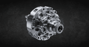
BTI engineers and manufactures a complete line of manual, semi-automatic, and fully automatic precision measurement and testing equipment for all types of transmission components
View More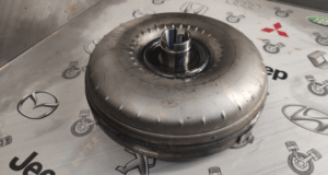
BTI engineers and manufactures a complete line of manual, semi-automatic, and fully automatic precision measurement and testing equipment for torque converters, turbines, dampers, stators, and all related assemblies and components
View More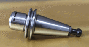
BTI engineers and manufactures both traditional spindled tool holder balancers and a patented (US Patent Numbers 5,763,777 and 5,965,815), first-of-its-kind, spindle-less balancer
View More
BTI engineers and manufactures a complete line of manual, semi-automatic, and fully automatic precision measurement and testing equipment for tire and tire/wheel assemblies for all wheel room applications
View More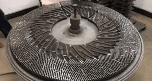
BTI engineers and manufactures a complete line of manual, semi-automatic, and fully automatic precision measurement and testing equipment for refiner plates
View More
BTI engineers and manufactures a complete line of manual, semi-automatic, and fully automatic precision measurement and testing equipment for pumps, fans, impellers, blowers, and related components
View More
BTI engineers and manufactures a complete line of manual, semi-automatic, and fully automatic precision measurement and testing equipment for all HVAC assemblies and related components
View More
BTI engineers and manufactures a complete line of manual, semi-automatic, and fully automatic precision measurement and testing equipment for hard drives, head readers, and related components
View More
BTI engineers and manufactures a complete line of manual, semi-automatic, and fully automatic precision measurement and testing equipment for all flywheels, flex plates, and related assemblies and components
View More
To contact us regarding your project - or if you have any questions - please click the button below :
Request a QuoteGet Started
Connect with our measurement experts and get the technical guidance your application demands.