
Electric Vehicle
BTI engineers and manufactures a complete line of manual, semi-automatic, and fully automatic precision measurement and testing equipment for all eDrive
View More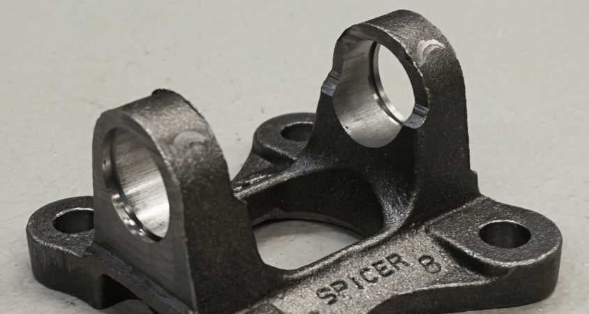
Flanges and yokes are small machined parts that decide whether a much larger assembly runs smoothly. A companion flange, a weld yoke or a slip yoke locates the driveshaft to the transmission and the axle, and any eccentricity it carries becomes runout and unbalance in a rotor several feet long.
Balance Technology Inc. builds balancing and dimensional measurement equipment for companion flanges, weld yokes, slip yokes, tube yokes and the end fittings used in driveline assemblies.
The mass of a yoke is trivial next to the driveshaft it joins, which leads people to discount it. What matters is not the mass but the geometry: the pilot diameter and the flange face locate the shaft, and an error there tilts or offsets the entire assembly.
A pilot machined eccentric to the bore by a small amount produces runout at the far end of the shaft that is larger than the original error, because the shaft amplifies an angular misalignment over its length. The same logic applies to a flange face that is not square to the axis.
These are machined forgings and castings, and the dominant sources are machining offset — the bore, pilot and face not concentric with one another — and the asymmetry designed into the part. Bolt hole patterns, grease fittings, keyways, splines and clamping ears are all deliberate departures from rotational symmetry, and they have to be accounted for rather than corrected away.
Forging flash variation and core shift in castings add a distributed contribution that machining does not remove.
Both approaches are used and they answer different questions. Balancing yokes and flanges as components catches parts that are out of family before they are welded or bolted into a shaft, which is cheap and prevents scrapping a finished assembly. Balancing the driveshaft assembly controls what the vehicle actually receives.
Production practice on a driveline usually does both: component control as a gate, assembly balance as acceptance. The component stage matters most where the assembly correction range is limited, because a yoke that arrives badly out of family can consume the entire weight budget on the shaft.
Material removal by drilling or milling on the flange face, the outside diameter or a designed boss is the usual method. The constraints are that the pilot, the bore, the bearing seats and the face must not be touched — those are locating surfaces — and that section thickness limits what can safely be taken from the rest.
Tolerances follow ISO 21940-11 from a balance quality grade, the component mass and the service speed. Because a yoke is light and runs at driveshaft speed, the permissible residual is small in absolute terms, and tooling contribution becomes a meaningful share of the budget. BTI publishes a free ISO 21940-11 balance tolerance calculator with the method behind it — grade selection, the permissible unbalance formula, plane allocation, and a worked example.
Balance and runout are separate characteristics, and on these parts runout is frequently the more consequential. Pilot concentricity, face squareness, bore-to-pilot relationship and spline condition all need gauging in their own right. A line that measures balance and not geometry will pass yokes that cause driveline vibration no balancing can fix.
Flange and yoke lines commonly combine balancing with:
Layouts range from single manual stations through to automated cells combining gauging, balancing and correction, and vary to accommodate any production rate. For platform selection across the full range, see BTI balancing machines.
Related applications include driveshafts, axles and RDU components and transmission components.
Are flanges and yokes balanced individually or as part of an assembly?
Both, depending on the application. A yoke that is welded to a driveshaft is normally balanced as part of that assembly. A bolt-on flange or a companion flange is often balanced on its own, because it may be replaced independently in service.
Why does a flange need balancing at all?
Because it is rotating mass at the end of a shaft, and asymmetry in it produces the same effect as asymmetry anywhere else on the rotor. Forged and cast flanges carry material variation, and machining does not necessarily remove it — it can move it.
Can a flange be balanced after it is bolted to a shaft?
If the assembly can be spun on its service axis, yes, and that gives the better result because it includes the fit between the two parts. Balancing the flange alone and then bolting it on leaves the joint’s contribution uncorrected.
What happens if a yoke is indexed differently on reassembly?
The unbalance correction no longer lines up. A driveshaft balanced with its yokes in a particular orientation must be reassembled the same way, which is why balanced assemblies are match-marked. Reassembling 180 degrees out can double the unbalance.
Does the bolt pattern affect balance?
It can. An odd number of bolt holes, or holes that are not perfectly evenly spaced, introduces asymmetry into the part. It is usually small relative to other sources, but on a precision application it forms part of the residual that has to be corrected.
Typical correction methods for balancing include drilling, milling, and manual and automatic welding.
Additionally, BTI’s unique ability to combine the aforementioned technologies into one fully integrated system enables our clients to reduce capital expenditures, increase product quality, and minimize floor space requirements.
Let our staff of more than 50 engineers design a configured-to-order solution for your specific requirements. Furthermore, our commercial Measurement & Testing Services Group (M&T Services) can assist with everything from prototype testing and R&D work to master certification and running small-to-medium production runs.
If you don’t see the product you are looking for, or have specific questions, please contact us.
BTI engineers and manufactures a complete line of manual, semi-automatic, and fully automatic precision measurement and testing equipment for all eDrive
View More
BTI engineers and manufactures a complete line of manual, semi-automatic, and fully automatic precision measurement and testing equipment for all turbo charger components and complete assemblies
View More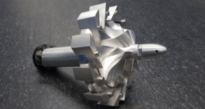
BTI engineers and manufactures a complete line of manual, semi-automatic, and fully automatic precision measurement and testing equipment for turbines, jet engines, blades, propellers, steam turbines, and other related assemblies and components weighing fractions of an ounce to 200,000 pounds
View More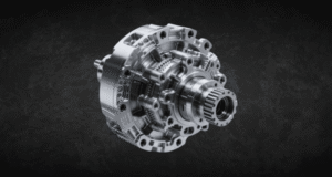
BTI engineers and manufactures a complete line of manual, semi-automatic, and fully automatic precision measurement and testing equipment for all types of transmission components
View More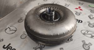
BTI engineers and manufactures a complete line of manual, semi-automatic, and fully automatic precision measurement and testing equipment for torque converters, turbines, dampers, stators, and all related assemblies and components
View More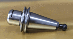
BTI engineers and manufactures both traditional spindled tool holder balancers and a patented (US Patent Numbers 5,763,777 and 5,965,815), first-of-its-kind, spindle-less balancer
View More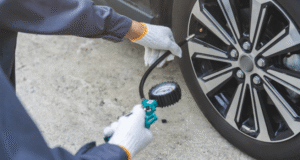
BTI engineers and manufactures a complete line of manual, semi-automatic, and fully automatic precision measurement and testing equipment for tire and tire/wheel assemblies for all wheel room applications
View More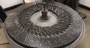
BTI engineers and manufactures a complete line of manual, semi-automatic, and fully automatic precision measurement and testing equipment for refiner plates
View More
BTI engineers and manufactures a complete line of manual, semi-automatic, and fully automatic precision measurement and testing equipment for pumps, fans, impellers, blowers, and related components
View More
BTI engineers and manufactures a complete line of manual, semi-automatic, and fully automatic precision measurement and testing equipment for all HVAC assemblies and related components
View More
BTI engineers and manufactures a complete line of manual, semi-automatic, and fully automatic precision measurement and testing equipment for hard drives, head readers, and related components
View More
BTI engineers and manufactures a complete line of manual, semi-automatic, and fully automatic precision measurement and testing equipment for all flywheels, flex plates, and related assemblies and components
View More
To contact us regarding your project - or if you have any questions - please click the button below :
Request a QuoteGet Started
Connect with our measurement experts and get the technical guidance your application demands.