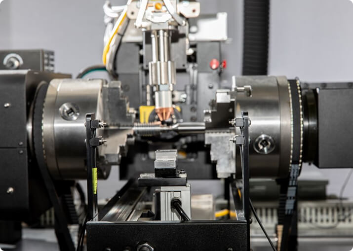

Electric Vehicle
BTI engineers and manufactures a complete line of manual, semi-automatic, and fully automatic precision measurement and testing equipment for all eDrive
View More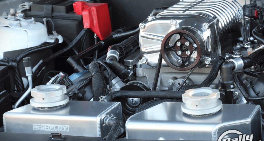
Turbochargers sit at the extreme end of the balancing problem. A passenger-car turbo core runs well beyond 100,000 rpm, and because permissible unbalance scales inversely with speed, the residual allowed on a part that small and that fast is very small indeed. It is also a rotor that does not stay still: it rides on a floating oil film, and its behavior at speed is not what a low-speed measurement predicts.
Balance Technology Inc. builds balancing and measurement equipment for turbocharger and supercharger components and assemblies — compressor wheels, turbine shaft assemblies, cores, and the rotors and housings of positive-displacement superchargers.
Turbocharger balancing is normally a two-stage process, and the stages answer different questions.
Component balancing handles the compressor wheel and the turbine shaft assembly individually, at low speed, on a conventional balancing machine. This catches gross casting and machining variation and brings each piece into a window before assembly. It is fast, repeatable and cheap.
Core balancing takes the assembled center housing rotating assembly and runs it at or near operating speed on an oil feed, measuring the vibration signature the way the engine will see it. This is the stage that catches what component balancing cannot: bearing clearance effects, oil film behavior, assembly stack-up and the shaft’s own dynamics under load.
Skipping the second stage is the common false economy. A core built from two individually balanced pieces can still be unacceptable, because the assembly introduces error the components never showed.
A turbo shaft does not run in rigid bearings. It runs on a hydrodynamic film in floating bearings, and the shaft center moves within the clearance as a function of speed, oil pressure and oil temperature. The rotor is also operating above critical speeds, so its response is modal rather than simply proportional.
This is why core balancing has to reproduce service conditions rather than approximate them. Oil supply pressure and temperature are process variables, not plumbing details, and a rig that does not control them will not produce a repeatable result.
Compressor wheels are corrected by removing material from the nose or the hub face, within limits the designer set. Turbine shaft assemblies are corrected at defined positions on the shaft or the wheel back face. In both cases the available material is small, the surfaces are aerodynamically or structurally significant, and the correction limits belong in the machine control so an out-of-family part is rejected rather than machined past specification.
Roots and screw superchargers do not share the turbocharger’s problem. They are lower-speed, positive-displacement machines with two meshed rotors, timing gears and tight inter-rotor clearances. Balance still matters — the rotors are long and the assembly is geared — but the dominant quality characteristics shift toward rotor profile, clearance control, timing and leak testing. Centrifugal superchargers behave more like turbochargers and are treated accordingly.
Tolerances follow ISO 21940-11 from a balance quality grade, the rotor mass and the service speed, and the high speeds involved make the grade selection consequential. BTI publishes a free ISO 21940-11 balance tolerance calculator with the method behind it — grade selection, the permissible unbalance formula, plane allocation, and a worked example.
Turbo lines typically combine balancing with:
Measurement repeatability matters more here than in most applications, because the tolerance band is narrow enough that an unstable fixture consumes a meaningful share of it.
Layouts range from single manual component stations through to automated cells combining component balance, core balance on oil, correction and data collection, and vary to accommodate any production rate. For platform selection across the full range, see BTI balancing machines.
Related applications include turbines, jet engines, blades and propellers and pumps, fans, impellers and blowers.
Why are turbocharger rotors balanced in two stages?
The wheels are balanced individually before assembly, then the assembled core is balanced again at speed. Component balancing removes the bulk of the unbalance while each piece can still be corrected freely. The assembled core still carries unbalance from stack-up, fit and the shaft itself, and that residue only shows at operating speed.
What speed are turbocharger rotors balanced at?
Component balancing happens at low speed. Core balancing is done at high speed, and modern automotive turbo cores are commonly balanced well above 100,000 RPM, with some applications reaching 300,000 RPM. The speed matters because the rotor’s behavior on its oil film is nothing like its behavior at rest.
Why does the oil film change the balancing result?
A turbocharger core runs on floating journal bearings supported by a pressurized oil film, not on rigid bearings. The shaft finds its own center within that film, so its effective axis of rotation at 150,000 RPM is not the axis it sits on statically. Balancing the core without oil, or without spinning it to speed, measures a condition the turbo never actually experiences.
How is a turbocharger wheel corrected when there is no spare material?
By removing small amounts from designated areas on the wheel back face or nose, within limits the designer has already allowed for. Compressor wheels are typically milled or drilled in a defined correction band. Because the available material is limited, component balancing before assembly matters more here than on almost any other rotor.
What causes turbocharger vibration after a rebuild?
Usually the core was reassembled without rebalancing, or the wheels were indexed differently from their original orientation. A turbo core is a matched assembly; changing the relationship between shaft, turbine wheel and compressor wheel changes the unbalance. Bearing wear and shaft bow also produce vibration that balancing alone will not resolve.
Do superchargers have the same balancing requirements?
No. A supercharger runs at a fraction of turbocharger speed, on conventional bearings, and its rotors are geometrically different — usually a pair of meshing rotors rather than a single shaft with two wheels. The tolerance is looser and the balancing method is closer to conventional two-plane rotor balancing.
Every machine below was designed, built and commissioned by BTI for turbocharger work. Each page carries the configuration, correction method and handling detail for that build.
Equipment layouts vary to accommodate any production rate. Typical correction methods for balancing include drilling, center drilling (mass centering), milling, and grinding.
Additionally, BTI’s unique ability to combine the aforementioned technologies into one fully integrated system enables our clients to reduce capital expenditures, increase product quality, and minimize floor space requirements.
Let our staff of more than 50 engineers design a configured-to-order solution for your specific requirements. Furthermore, our commercial Measurement & Testing Services Group (M&T Services) can assist with everything from prototype testing and R&D work to master certification and running small-to-medium production runs.
If you don’t see the product you are looking for, or have specific questions, please contact us.
BTI engineers and manufactures a complete line of manual, semi-automatic, and fully automatic precision measurement and testing equipment for all eDrive
View More
BTI engineers and manufactures a complete line of manual, semi-automatic, and fully automatic precision measurement and testing equipment for turbines, jet engines, blades, propellers, steam turbines, and other related assemblies and components weighing fractions of an ounce to 200,000 pounds
View More
BTI engineers and manufactures a complete line of manual, semi-automatic, and fully automatic precision measurement and testing equipment for all types of transmission components
View More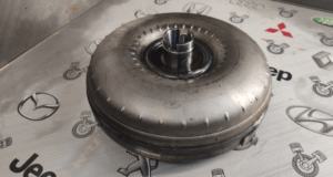
BTI engineers and manufactures a complete line of manual, semi-automatic, and fully automatic precision measurement and testing equipment for torque converters, turbines, dampers, stators, and all related assemblies and components
View More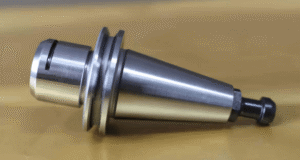
BTI engineers and manufactures both traditional spindled tool holder balancers and a patented (US Patent Numbers 5,763,777 and 5,965,815), first-of-its-kind, spindle-less balancer
View More
BTI engineers and manufactures a complete line of manual, semi-automatic, and fully automatic precision measurement and testing equipment for tire and tire/wheel assemblies for all wheel room applications
View More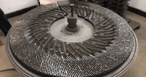
BTI engineers and manufactures a complete line of manual, semi-automatic, and fully automatic precision measurement and testing equipment for refiner plates
View More
BTI engineers and manufactures a complete line of manual, semi-automatic, and fully automatic precision measurement and testing equipment for pumps, fans, impellers, blowers, and related components
View More
BTI engineers and manufactures a complete line of manual, semi-automatic, and fully automatic precision measurement and testing equipment for all HVAC assemblies and related components
View More
BTI engineers and manufactures a complete line of manual, semi-automatic, and fully automatic precision measurement and testing equipment for hard drives, head readers, and related components
View More
BTI engineers and manufactures a complete line of manual, semi-automatic, and fully automatic precision measurement and testing equipment for all flywheels, flex plates, and related assemblies and components
View More
BTI engineers and manufactures a complete line of manual, semi-automatic, and fully automatic precision measurement and testing equipment for flanges, yokes, and related assemblies and components
View More
To contact us regarding your project - or if you have any questions - please click the button below :
Request a QuoteGet Started
Connect with our measurement experts and get the technical guidance your application demands.