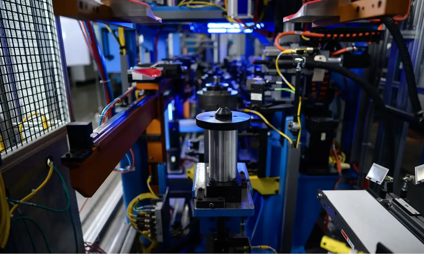

Electric Vehicle
BTI engineers and manufactures a complete line of manual, semi-automatic, and fully automatic precision measurement and testing equipment for all eDrive
View More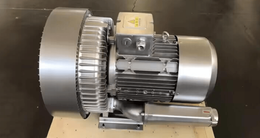
Pumps, fans, impellers and blowers cover more rotor geometries than any other category on this site, and the single decision that matters most is also the one most often made by habit: one correction plane or two.
Balance Technology Inc. builds manual, semi-automatic and fully automatic balancing and measurement equipment for centrifugal and axial fans, pump impellers, blower wheels, and the shafts and hubs they mount on.
A disc-shaped rotor (large in diameter, short along its axis) can usually be corrected in a single plane, because there is not enough axial separation for a meaningful couple to develop. A rotor with appreciable axial length cannot, and correcting it in one plane leaves a couple that produces vibration at the bearings even when the static unbalance reads near zero.
The decision comes from the diameter-to-length ratio and the service speed together, not from either alone. A wide fan wheel that would be single-plane at low speed becomes a two-plane problem as speed rises, because the couple’s effect grows with the square of speed while the tolerance shrinks. Where a part sits near the boundary, two-plane is the safe answer.
The two dominant constructions fail differently.
Fabricated and welded fan wheels carry unbalance from blade placement variation and from weld distortion. The distortion is the awkward part: it is introduced after the components were within tolerance, and it can continue to relax after balancing if the assembly is not stress-relieved. A wheel balanced immediately after welding may not stay balanced.
Cast impellers carry unbalance from wall thickness variation, core shift and porosity. That unbalance is distributed through the body rather than concentrated, and a casting that is badly out of family is often better rejected than corrected, because the correction needed exceeds what the material will safely give up.
Removal by drilling or grinding on a hub, shroud or balance boss is the usual method where material exists to lose. On thin shrouds and cast bodies it frequently does not, and correction moves to added mass: welded weights on fabricated wheels, or weights into designed pockets.
The limits are structural and hydraulic. Material removed from a blade or a shroud changes the flow as well as the mass distribution, and on a pump that can be a performance change rather than a cosmetic one. Correction limits belong in the machine control so an out-of-family part is rejected rather than machined into a problem.
This is the category where in-service change matters most. Erosion, corrosion, product build-up and impact damage all alter mass distribution over a service life, and a wheel that left the factory in tolerance can be well outside it after a year in an abrasive or fouling duty.
That has two consequences. Field rebalancing is a normal part of the equipment’s life rather than a failure, and the tolerance chosen at manufacture should leave some margin for the degradation the duty will impose.
ISO 21940-11 places pump impellers and fans in different balance quality grades, with pumps generally finer than fans, and the permissible unbalance follows from that grade together with the rotor mass and the service speed. BTI publishes a free ISO 21940-11 balance tolerance calculator alongside the method: grade selection, the permissible unbalance formula, allocation across planes, and a worked example.
A caution for overhung rotors: the permissible unbalance allocated to each plane is not simply half the total when the correction planes are unequally spaced from the bearings. The allocation follows the geometry.
Most wheels in this category are balanced on a mandrel or an arbor rather than on their own shaft, and the mandrel carries unbalance and runout of its own that add to the part vectorially. A bent or worn mandrel produces a stable, repeatable, wrong answer. An index test settles it: measure as mounted, rotate the part 180 degrees relative to the tooling, re-clamp and measure again. Half the vector difference is the part; half the vector sum is the tooling.
Depending on the duty and the failure modes being controlled, equipment for this application also covers:
Layouts range from single manual stations for repair and low-volume work through to automated cells with correction and data collection, and vary to accommodate any production rate. For platform selection across the full range, see BTI balancing machines.
Related applications include HVAC assemblies, turbines, jet engines, blades and propellers and refiner plates.
Usually in a single plane for a narrow impeller, two planes for a wider one. The impeller is located on its bore and keyway or on the shaft it will run on, spun, and corrected by grinding or milling material from the shroud, hub or vane tips, or by adding weights where the design allows.
On its own shaft where practical, because that is the axis it will turn on in service. An arbor introduces its own runout and clearance, and an impeller balanced on an arbor then fitted to a shaft with a different fit can carry more unbalance than it started with.
Because casting leaves wall thickness variation that no amount of dimensional inspection catches. A cast impeller can be within every dimensional tolerance on the print and still be significantly out of balance, because the variation is inside the material rather than on its surfaces.
It comes from the balance quality grade and the maximum service speed. Fans and blowers commonly sit in the G 6.3 range, with large industrial fans sometimes looser and high-speed blowers tighter. The permissible residual unbalance follows from the grade, the mass and the speed together.
Yes, and it is often necessary. Erosion, corrosion, deposit buildup and impact damage all change mass distribution. An impeller that has been cleaned or repaired should be rebalanced before it returns to service, because the repair itself redistributes mass.
Because unbalance is only one source. Aerodynamic excitation, blade passing frequency, shaft misalignment, bearing condition, and resonance in the fan housing or ductwork all produce vibration that balancing cannot address. A fan that reads well on the balancer and badly in the plant usually has an installation or resonance problem.
Typical correction methods for balancing include drilling, milling, grinding, and projection and spot welding of weights.
Additionally, BTI’s unique ability to combine the aforementioned technologies into one fully integrated system enables our clients to reduce capital expenditures, increase product quality, and minimize floor space requirements.
Let our staff of more than 50 engineers design a configured-to-order solution for your specific requirements. Furthermore, our commercial Measurement & Testing Services Group (M&T Services) can assist with everything from prototype testing and R&D work to master certification and running small-to-medium production runs.
If you don’t see the product you are looking for, or have specific questions, please contact us.
BTI engineers and manufactures a complete line of manual, semi-automatic, and fully automatic precision measurement and testing equipment for all eDrive
View More
BTI engineers and manufactures a complete line of manual, semi-automatic, and fully automatic precision measurement and testing equipment for all turbo charger components and complete assemblies
View More
BTI engineers and manufactures a complete line of manual, semi-automatic, and fully automatic precision measurement and testing equipment for turbines, jet engines, blades, propellers, steam turbines, and other related assemblies and components weighing fractions of an ounce to 200,000 pounds
View More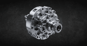
BTI engineers and manufactures a complete line of manual, semi-automatic, and fully automatic precision measurement and testing equipment for all types of transmission components
View More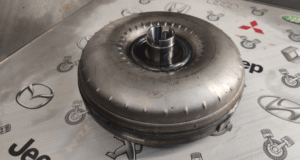
BTI engineers and manufactures a complete line of manual, semi-automatic, and fully automatic precision measurement and testing equipment for torque converters, turbines, dampers, stators, and all related assemblies and components
View More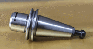
BTI engineers and manufactures both traditional spindled tool holder balancers and a patented (US Patent Numbers 5,763,777 and 5,965,815), first-of-its-kind, spindle-less balancer
View More
BTI engineers and manufactures a complete line of manual, semi-automatic, and fully automatic precision measurement and testing equipment for tire and tire/wheel assemblies for all wheel room applications
View More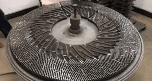
BTI engineers and manufactures a complete line of manual, semi-automatic, and fully automatic precision measurement and testing equipment for refiner plates
View More
BTI engineers and manufactures a complete line of manual, semi-automatic, and fully automatic precision measurement and testing equipment for all HVAC assemblies and related components
View More
BTI engineers and manufactures a complete line of manual, semi-automatic, and fully automatic precision measurement and testing equipment for hard drives, head readers, and related components
View More
BTI engineers and manufactures a complete line of manual, semi-automatic, and fully automatic precision measurement and testing equipment for all flywheels, flex plates, and related assemblies and components
View More
BTI engineers and manufactures a complete line of manual, semi-automatic, and fully automatic precision measurement and testing equipment for flanges, yokes, and related assemblies and components
View More
To contact us regarding your project - or if you have any questions - please click the button below :
Request a QuoteGet Started
Connect with our measurement experts and get the technical guidance your application demands.