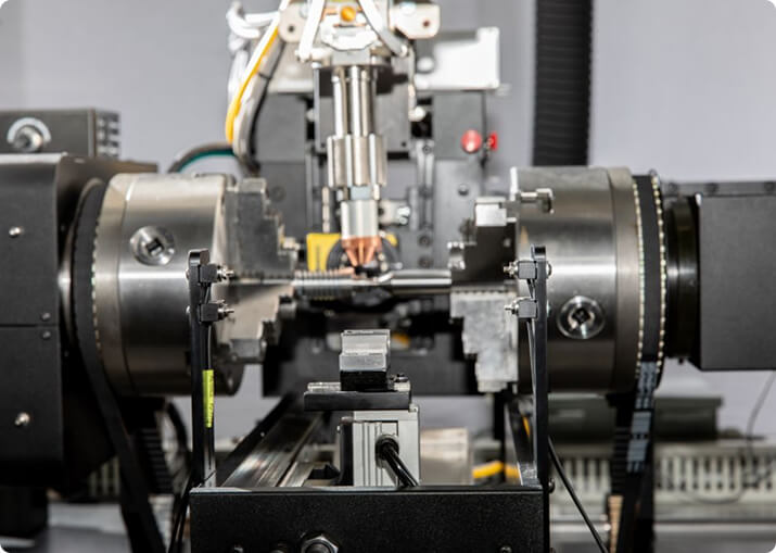

Electric Vehicle
BTI engineers and manufactures a complete line of manual, semi-automatic, and fully automatic precision measurement and testing equipment for all eDrive
View More
A transmission is a collection of rotors that do not share a speed. Input shafts turn at engine speed, output shafts at road speed, planetary members at ratios in between, and each rotating member has its own permissible unbalance because permissible unbalance depends on the speed that member actually sees.
Balance Technology Inc. builds manual, semi-automatic and fully automatic balancing, gauging and test equipment for transmission components — input and output shafts, clutch drums and hubs, planetary carriers, flexplates and complete rotating assemblies.
This is the mistake worth designing out of a process sheet. Because permissible unbalance scales inversely with speed, a light component running fast can have a tighter requirement than a heavy one running slowly. A transmission input shaft and an output shaft of similar mass can carry meaningfully different tolerances, and applying one number across the family will be wrong in both directions.
BTI publishes a free ISO 21940-11 balance tolerance calculator together with the method — grade selection, the permissible unbalance formula, plane allocation, and a worked example, so the arithmetic can be done per member rather than assumed.
Shafts are long relative to their diameter. They are two-plane rotors, they can develop a couple even when the static unbalance reads near zero, and the longer and faster ones need checking against their bending critical speed before a rigid-rotor tolerance is applied to them.
Clutch drums, hubs and carriers are disc-like. Most are single-plane parts, and their unbalance comes from casting or forming variation, spline and window machining, and the asymmetry designed into them for oil feed and retention.
Treating both as the same kind of rotor because they arrive at the same station is how couples get missed.
Balancing components individually controls the inputs. It does not control what happens when they go together, because the residuals combine vectorially and can cancel or compound depending on the relative angular position at assembly.
Where the assembly matters — and in a transmission it usually does — the practical answers are either to balance the assembly as it will run, or to control the assembly orientation so that residuals are indexed rather than random. Choosing neither and hoping the components average out is the common failure.
Rotating clutch drums fill and empty with fluid in service, and a drum that is balanced dry is not necessarily balanced with a partial fluid charge distributed by centrifugal force. In most production contexts the component is measured dry and the design accounts for the running condition, but it is worth knowing that the two states are not identical, and that residual fluid left in a part from a previous operation will give an unrepeatable reading.
Drilling or milling on a drum face, a hub boss or a designed balance land is the usual removal method. On shafts the available material is often limited by spline and bearing features, and correction may move to designed flats or to added weights at defined positions. Correction limits belong in the machine control so an out-of-family part is rejected rather than machined into a bearing journal or an oil passage.
Most transmission noise complaints are gear mesh, bearing condition, or housing and mounting resonance rather than unbalance. Gear whine is tonal and is noticed at low amplitude in a way that broadband noise is not, which makes order-resolved measurement more informative than an overall vibration number on an assembled unit.
Balance remains worth controlling tightly precisely because it is the contributor that can be measured and fixed cheaply on the component, before value is added.
Transmission lines commonly combine balancing with:
Layouts range from single manual stations through to fully automatic cells with correction, part identification and data collection across the line, and vary to accommodate any production rate. For platform selection across the full range, see BTI balancing machines.
Related applications include torque converters and components, clutches and components and flywheels and flex plates.
What transmission components need balancing?
The rotating assemblies that turn at engine speed or above: input shafts, clutch drums, planetary carriers, torque converters, and on some designs the output shaft. Gears themselves are generally not balanced as individual parts, but the shaft assemblies that carry them are.
Why are transmission shafts balanced in two planes?
Because they are long relative to their diameter and carry mass at both ends. Unbalance at the input end and unbalance at the output end form a couple that single-plane correction cannot remove. The geometry decides the number of planes, not the component’s name.
Should a transmission be balanced as an assembly?
No. Once the components are inside the case there is no access to correct unbalance and no single axis to measure about. Balance is established on the individual rotating assemblies before build; the completed transmission is then verified by noise and vibration testing.
What causes transmission noise that balancing will not fix?
Gear mesh, bearing condition, shaft misalignment, case resonance, and backlash outside specification. Unbalance produces a once-per-revolution excitation; gear mesh produces tones at the tooth passing frequency. They sound different and they have different causes, and telling them apart is the first step in diagnosing a complaint.
Are automatic and manual transmissions balanced differently?
The rotating assemblies differ but the method does not. An automatic carries the torque converter, clutch drums and planetary sets; a manual carries the clutch, countershaft and synchronizer assemblies. Each is balanced according to its own geometry and speed.
What else is measured on transmission components?
End play, backlash, torque to turn, runout and concentricity, and often leak integrity on the assembled unit. Several of these can be measured in the same cycle as balancing when the component is already located on a precise axis and rotating.
Additionally, BTI’s unique ability to combine the aforementioned technologies into one fully integrated system enables our clients to reduce capital expenditures, increase product quality, and minimize floor space requirements.
Let our staff of more than 50 engineers design a configured-to-order solution for your specific requirements. Furthermore, our commercial Measurement & Testing Services Group (M&T Services) can assist with everything from prototype testing and R&D work to master certification and running small-to-medium production runs.
If you don’t see the product you are looking for, or have specific questions, please contact us.
BTI engineers and manufactures a complete line of manual, semi-automatic, and fully automatic precision measurement and testing equipment for all eDrive
View More
BTI engineers and manufactures a complete line of manual, semi-automatic, and fully automatic precision measurement and testing equipment for all turbo charger components and complete assemblies
View More
BTI engineers and manufactures a complete line of manual, semi-automatic, and fully automatic precision measurement and testing equipment for turbines, jet engines, blades, propellers, steam turbines, and other related assemblies and components weighing fractions of an ounce to 200,000 pounds
View More
BTI engineers and manufactures a complete line of manual, semi-automatic, and fully automatic precision measurement and testing equipment for torque converters, turbines, dampers, stators, and all related assemblies and components
View More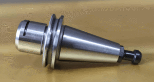
BTI engineers and manufactures both traditional spindled tool holder balancers and a patented (US Patent Numbers 5,763,777 and 5,965,815), first-of-its-kind, spindle-less balancer
View More
BTI engineers and manufactures a complete line of manual, semi-automatic, and fully automatic precision measurement and testing equipment for tire and tire/wheel assemblies for all wheel room applications
View More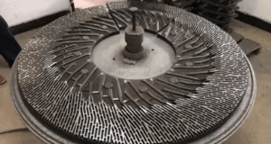
BTI engineers and manufactures a complete line of manual, semi-automatic, and fully automatic precision measurement and testing equipment for refiner plates
View More
BTI engineers and manufactures a complete line of manual, semi-automatic, and fully automatic precision measurement and testing equipment for pumps, fans, impellers, blowers, and related components
View More
BTI engineers and manufactures a complete line of manual, semi-automatic, and fully automatic precision measurement and testing equipment for all HVAC assemblies and related components
View More
BTI engineers and manufactures a complete line of manual, semi-automatic, and fully automatic precision measurement and testing equipment for hard drives, head readers, and related components
View More
BTI engineers and manufactures a complete line of manual, semi-automatic, and fully automatic precision measurement and testing equipment for all flywheels, flex plates, and related assemblies and components
View More
BTI engineers and manufactures a complete line of manual, semi-automatic, and fully automatic precision measurement and testing equipment for flanges, yokes, and related assemblies and components
View More
To contact us regarding your project - or if you have any questions - please click the button below :
Request a QuoteGet Started
Connect with our measurement experts and get the technical guidance your application demands.