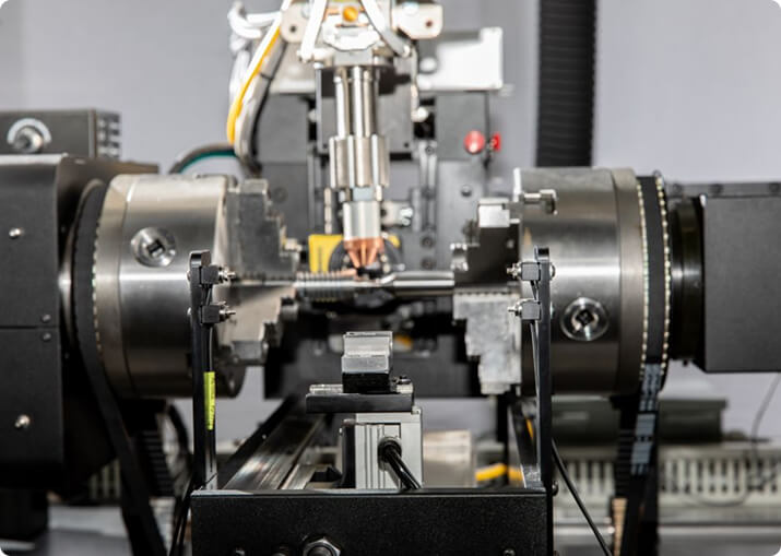

Electric Vehicle
BTI engineers and manufactures a complete line of manual, semi-automatic, and fully automatic precision measurement and testing equipment for all eDrive
View More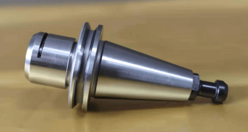
A machine tool spindle assembly is the rotor where balance turns directly into product quality. Everything the spindle carries — holder, collet, retention knob, cutting tool — rotates with it, and at the speeds modern machining centers run, a residual that would be invisible on a driveshaft shows up as chatter marks on the part and as bearing life you do not get back.
Balance Technology Inc. builds balancing and measurement equipment for machine tool spindles, tool holders and holder-and-tool assemblies.
Permissible unbalance scales inversely with speed, so a holder that is comfortable at 8,000 rpm can be unacceptable at 24,000. Meanwhile the centrifugal force from a given residual rises with the square of speed. Those two effects compound: as spindle speeds climbed, the tolerable residual fell and the penalty for exceeding it grew at the same time.
The practical consequence is that high-speed tooling has to be balanced as a matter of course rather than as a remedy, and the balance grade has to be stated at a specific speed to mean anything.
A tool holder balanced empty tells you very little. The assembly that runs in the spindle includes the cutting tool, the collet or chuck, the retention knob or pull stud, and any setscrews — and several of those are inherently asymmetric.
An end mill has flutes. A setscrew is mass on one side. A boring head is deliberately offset.
So the meaningful measurement is of the assembly as it will run, with the actual tool in it, and the balance condition does not survive a tool change. A shop that balances holders and then swaps cutters is measuring something it is not using.
HSK, CAT, BT and similar tapers locate the holder to the spindle, and the repeatability of that interface sets the repeatability of everything downstream. A holder measured in a fixture that does not reproduce the spindle’s clamping force and contact condition will give a reading the machine does not reproduce.
Taper condition matters too. Fretting, dirt or damage in the taper changes seating from one clamp to the next, and produces a balance reading that will not repeat no matter how good the machine is. Cleanliness at the interface is a measurement variable, not housekeeping.
Purpose-built holders carry designed correction features: balance rings with adjustable elements, radial setscrews at known positions, or machined balance lands. These allow correction without touching structural or locating surfaces, and they can be readjusted when the tool changes.
Material removal on the holder body is available where the design allows it, but it is permanent and the body has limited spare material. Neither the taper nor the flange face is correctable — those are locating surfaces.
Tooling tolerances follow ISO 21940-11 from a balance quality grade, the assembly mass and the maximum operating speed. Machine tool practice normally sits at fine grades, and because the mass is small the permissible residual comes out very small in absolute terms — which makes tooling and fixture contributions a significant share of the budget.
BTI publishes a free ISO 21940-11 balance tolerance calculator with the method behind it — grade selection, the permissible unbalance formula, plane allocation, and a worked example. State the speed with the grade; a grade alone is not a specification.
Short, stubby holders are often single-plane parts. Long holders, extensions and slender boring bars are not: they have real axial length, they run fast, and the couple matters. They may also need checking against their bending critical speed, since a long, thin tool assembly can behave as a flexible rotor at the top of its speed range.
Spindle and tooling work commonly combines balancing with:
Runout and balance are separate characteristics and neither predicts the other.
Layouts range from single manual stations for a toolroom or a tool crib through to automated cells for holder manufacturers, and vary to accommodate any production rate. For platform selection across the full range, see BTI balancing machines.
Related applications include armatures, rotors and motor assemblies and other applications.
Why do spindles and tool holders need balancing?
Because they turn fast enough that small unbalance produces large forces. At 20,000 RPM a few gram-millimeters of unbalance generates enough radial load to degrade surface finish, shorten spindle bearing life and reduce tool life. The faster the spindle, the more the residual unbalance matters.
What balance grade applies to a tool holder?
High-speed tool holders are commonly specified to G 2.5 or tighter, and some ultra-high-speed applications call for G 1 or better. The permissible residual unbalance falls quickly as speed rises, which is why a holder that is acceptable at 8,000 RPM may not be at 24,000.
Should a tool holder be balanced with the tool in it?
Ideally yes. The cutting tool, collet and retention knob all contribute unbalance, and a holder balanced empty carries an uncorrected contribution once it is loaded. Where that is impractical, holders are balanced alone to a tight grade and the tool assembly is checked separately.
How are tool holders corrected?
Usually by adjustable balance rings or set screws built into the holder, which allow correction without machining. Where material is removed, it is taken from defined areas designed for the purpose. Cutting into the taper or the gauge surfaces is never acceptable.
Does spindle balance affect surface finish?
Directly. Residual unbalance produces a once-per-revolution radial deflection at the tool tip, which transfers into the workpiece as a periodic variation in the cut. On fine finishing operations this is often the limiting factor, and it appears as a regular pattern on the machined surface.
Additionally, BTI’s unique ability to combine the aforementioned technologies into one fully integrated system enables our clients to reduce capital expenditures, increase product quality, and minimize floor space requirements.
Let our staff of more than 50 engineers design a configured-to-order solution for your specific requirements. Furthermore, our commercial Measurement & Testing Services Group (M&T Services) can assist with everything from prototype testing and R&D work to master certification and running small-to-medium production runs.
If you don’t see the product you are looking for, or have specific questions, please contact us.
BTI engineers and manufactures a complete line of manual, semi-automatic, and fully automatic precision measurement and testing equipment for all eDrive
View More
BTI engineers and manufactures a complete line of manual, semi-automatic, and fully automatic precision measurement and testing equipment for all turbo charger components and complete assemblies
View More
BTI engineers and manufactures a complete line of manual, semi-automatic, and fully automatic precision measurement and testing equipment for turbines, jet engines, blades, propellers, steam turbines, and other related assemblies and components weighing fractions of an ounce to 200,000 pounds
View More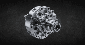
BTI engineers and manufactures a complete line of manual, semi-automatic, and fully automatic precision measurement and testing equipment for all types of transmission components
View More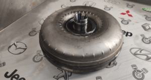
BTI engineers and manufactures a complete line of manual, semi-automatic, and fully automatic precision measurement and testing equipment for torque converters, turbines, dampers, stators, and all related assemblies and components
View More
BTI engineers and manufactures a complete line of manual, semi-automatic, and fully automatic precision measurement and testing equipment for tire and tire/wheel assemblies for all wheel room applications
View More
BTI engineers and manufactures a complete line of manual, semi-automatic, and fully automatic precision measurement and testing equipment for refiner plates
View More
BTI engineers and manufactures a complete line of manual, semi-automatic, and fully automatic precision measurement and testing equipment for pumps, fans, impellers, blowers, and related components
View More
BTI engineers and manufactures a complete line of manual, semi-automatic, and fully automatic precision measurement and testing equipment for all HVAC assemblies and related components
View More
BTI engineers and manufactures a complete line of manual, semi-automatic, and fully automatic precision measurement and testing equipment for hard drives, head readers, and related components
View More
BTI engineers and manufactures a complete line of manual, semi-automatic, and fully automatic precision measurement and testing equipment for all flywheels, flex plates, and related assemblies and components
View More
BTI engineers and manufactures a complete line of manual, semi-automatic, and fully automatic precision measurement and testing equipment for flanges, yokes, and related assemblies and components
View More
To contact us regarding your project - or if you have any questions - please click the button below :
Request a QuoteGet Started
Connect with our measurement experts and get the technical guidance your application demands.