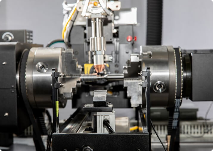

Electric Vehicle
BTI engineers and manufactures a complete line of manual, semi-automatic, and fully automatic precision measurement and testing equipment for all eDrive
View More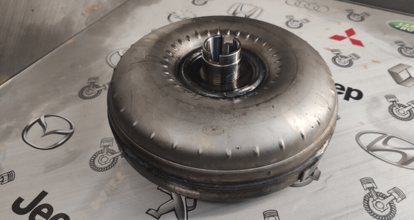
A torque converter is a welded pressure vessel full of fluid that runs at engine speed, and almost all of its unbalance is created by the operation that closes it. The impeller, turbine and stator can each be within tolerance individually, and the assembly can still be well outside it once the cover is welded on, because welding distorts.
Balance Technology Inc. builds manual, semi-automatic and fully automatic balancing, leak testing and measurement equipment for torque converters, converter covers, impellers, turbines and lock-up clutch assemblies.
This is the single most consequential sequencing decision on a converter line. The cover-to-impeller weld is a full circumferential joint on a thin stamped shell, and it introduces both distortion and weld metal that were not there when the components were measured.
A converter balanced at component level and then welded is not a balanced converter. Component balancing still has a role — it catches stampings and turbine assemblies that are grossly out of family before value is added — but the acceptance measurement belongs after the last weld.
Converters run full of transmission fluid, and the fluid mass is a significant fraction of the assembly. It is not, however, part of the balance measurement: production units are measured dry, and the design accounts for the running condition.
What does matter is that residual fluid from a previous operation — leak test, flushing, or a returned core in remanufacturing — will move under rotation and give a reading that does not repeat. Draining matters before measuring.
The shell is thin, it is structural, and it is the wall of a pressure vessel. Drilling into it is not available. Correction is by adding mass, normally weights welded or projection-welded to the cover or the impeller shell at a defined angular position.
Three consequences follow. Correction resolution is set by the discrete weight sizes available. Weld placement repeatability becomes balance repeatability directly. And the correction weld must not compromise the shell — a converter that leaks because of a balance weight is a worse outcome than the unbalance it removed.
Most converters are treated as single-plane rotors: they are large in diameter relative to their axial length, and the dominant condition is static. Longer units, and assemblies where the turbine and lock-up clutch sit well away from the cover plane, justify checking whether a couple is present rather than assuming it is not.
A converter turns at engine speed, so the permissible unbalance follows from that speed together with the assembly mass and a balance quality grade under ISO 21940-11. BTI publishes a free ISO 21940-11 balance tolerance calculator with the method behind it — grade selection, the permissible unbalance formula, plane allocation, and a worked example.
Watch whether a specification is stated per plane or for the assembly as a whole, and watch the units: one ounce-inch is 720 gram-millimeters, and a figure written down without units is a hazard rather than a specification.
A converter locates on its hub and its pilot, and the tooling has to hold it on the same features the transmission and crankshaft will. Hub runout, pilot condition and the flatness of the mounting pads are part of what the machine reads, and a converter with a damaged pilot will not give a repeatable number.
An index test separates part from tooling: measure as mounted, rotate 180 degrees relative to the fixture, re-clamp and measure again. Half the vector difference is the part; half the vector sum is the tooling.
Converter lines rarely measure balance alone. Leak testing is normally the critical station, since the unit is a welded pressure vessel. Lines also commonly include:
Layouts range from single manual stations for remanufacturing through to fully automatic cells combining leak test, balance, weld correction and data collection, and vary to accommodate any production rate. For platform selection across the full range, see BTI balancing machines.
Related applications include transmission components, clutches and components and flywheels and flex plates.
How is a torque converter balanced?
A torque converter is balanced as a welded assembly, typically in one or two planes depending on its proportions, with correction made by adding weights to the cover or by removing material from designated areas. Because the converter is a sealed fluid coupling, the balance must be established with the assembly complete.
Why do torque converters go out of balance during manufacture?
The converter is a weldment made from several stampings, and the welding itself introduces asymmetry. Impeller and turbine blade sets vary slightly, the cover and the impeller shell are not perfectly concentric after welding, and the lockup clutch assembly adds mass that may not be centered. Each of these is small; together they exceed what the transmission will tolerate.
Should a torque converter be balanced with fluid in it?
Generally no. Balancing is done dry, because fluid mass redistributes with speed and does not contribute a fixed unbalance vector. What matters is that the rotating metal is balanced; the fluid finds its own distribution in service.
What happens if a torque converter is out of balance?
Vibration transmitted directly into the transmission case and through the driveline, usually felt as a speed-dependent shake. Because the converter sits between the engine and transmission, its unbalance loads the crankshaft thrust face and the transmission input bearing. Sustained operation with an out-of-balance converter shortens the life of both.
Can a torque converter be rebalanced after rebuilding?
Yes, and it should be. A rebuilt converter has been cut open and rewelded, which changes its mass distribution. Any converter that has been opened needs to be rebalanced before it goes back into service.
Is balancing enough on its own for a torque converter?
No. Converters are also checked for runout, pilot and pump drive concentricity, and leak integrity. A converter that is perfectly balanced but running out at the pilot will still vibrate, because the assembly is no longer rotating about the axis the transmission holds it on.
Typical correction methods for balancing vary by product type, and include projection and spot welding, milling, drilling, and piercing.
BTI’s torque converter assembly balancers are capable of measuring unbalance in three modes: static internal method, 180-degree flip method, and differential method, which yields fast and more accurate results.
Additionally, BTI’s unique ability to combine the aforementioned technologies into one fully integrated system enables our clients to reduce capital expenditures, increase product quality, and minimize floor space requirements.
Let our staff of more than 50 engineers design a configured-to-order solution for your specific requirements. Furthermore, our commercial Measurement & Testing Services Group (M&T Services) can assist with everything from prototype testing and R&D work to master certification and running small-to-medium production runs.
If you don’t see the product you are looking for, or have specific questions, please contact us.
BTI engineers and manufactures a complete line of manual, semi-automatic, and fully automatic precision measurement and testing equipment for all eDrive
View More
BTI engineers and manufactures a complete line of manual, semi-automatic, and fully automatic precision measurement and testing equipment for all turbo charger components and complete assemblies
View More
BTI engineers and manufactures a complete line of manual, semi-automatic, and fully automatic precision measurement and testing equipment for turbines, jet engines, blades, propellers, steam turbines, and other related assemblies and components weighing fractions of an ounce to 200,000 pounds
View More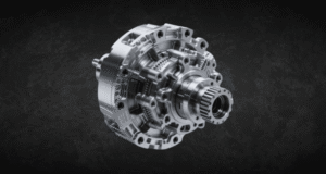
BTI engineers and manufactures a complete line of manual, semi-automatic, and fully automatic precision measurement and testing equipment for all types of transmission components
View More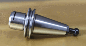
BTI engineers and manufactures both traditional spindled tool holder balancers and a patented (US Patent Numbers 5,763,777 and 5,965,815), first-of-its-kind, spindle-less balancer
View More
BTI engineers and manufactures a complete line of manual, semi-automatic, and fully automatic precision measurement and testing equipment for tire and tire/wheel assemblies for all wheel room applications
View More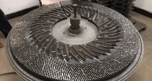
BTI engineers and manufactures a complete line of manual, semi-automatic, and fully automatic precision measurement and testing equipment for refiner plates
View More
BTI engineers and manufactures a complete line of manual, semi-automatic, and fully automatic precision measurement and testing equipment for pumps, fans, impellers, blowers, and related components
View More
BTI engineers and manufactures a complete line of manual, semi-automatic, and fully automatic precision measurement and testing equipment for all HVAC assemblies and related components
View More
BTI engineers and manufactures a complete line of manual, semi-automatic, and fully automatic precision measurement and testing equipment for hard drives, head readers, and related components
View More
BTI engineers and manufactures a complete line of manual, semi-automatic, and fully automatic precision measurement and testing equipment for all flywheels, flex plates, and related assemblies and components
View More
BTI engineers and manufactures a complete line of manual, semi-automatic, and fully automatic precision measurement and testing equipment for flanges, yokes, and related assemblies and components
View More
To contact us regarding your project - or if you have any questions - please click the button below :
Request a QuoteGet Started
Connect with our measurement experts and get the technical guidance your application demands.