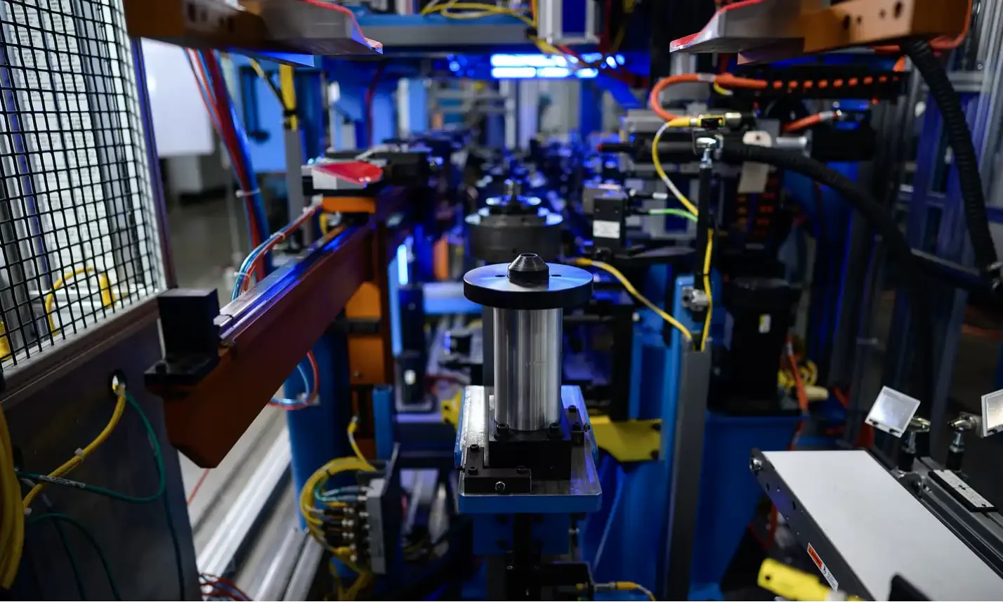

Electric Vehicle
BTI engineers and manufactures a complete line of manual, semi-automatic, and fully automatic precision measurement and testing equipment for all eDrive
View More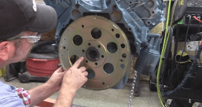
A flywheel looks like the simplest rotor in an engine and it carries one of the most misunderstood specifications. For an externally balanced engine, the flywheel is not supposed to be balanced to zero. It is supposed to carry a specified unbalance, because it is part of the crankshaft’s balance system rather than an independent rotor.
Balance Technology Inc. builds manual, semi-automatic and fully automatic balancing and measurement equipment for flywheels, flex plates, dual-mass flywheels and the ring gears and clutch surfaces that go with them.
On an internally balanced engine the crankshaft carries all of its own correction, and the flywheel is balanced to as near zero as the tolerance allows. On an externally balanced engine the crankshaft is deliberately left with a residual, and the flywheel and damper carry offsetting mass by design.
That distinction decides the whole process. A flywheel for an externally balanced application measured against a zero target will be rejected as grossly unbalanced when it is exactly correct. The target is a specified amount at a specified angle relative to a datum feature, and the datum matters as much as the amount.
It also means these parts cannot be interchanged between engine families that look otherwise identical, and a production line handling both needs the part identification to drive the acceptance criteria rather than relying on operator memory.
A flywheel is a disc: large in diameter, short along its axis. There is rarely enough axial separation for a meaningful couple to develop, so single-plane correction is normally sufficient. Thick flywheels and dual-mass assemblies are the exceptions and want checking rather than assuming.
The clutch face is a functional friction surface with a flatness and finish specification, and correction cannot come from it. Drilling or milling removes material from the back face, the outer rim or designed bosses, within limits set by section thickness and by the stresses a flywheel sees at speed.
Flex plates change the problem completely. They are thin stamped steel, flexible by design, and there is no material to remove. Correction is by weights attached at designed locations, and the plate’s own flatness and distortion become part of the measurement: a flex plate that is not flat will not give a repeatable reading on any machine.
The ring gear is normally an interference fit, and it can sit slightly eccentric to the flywheel axis. That produces runout and, because the ring gear is a significant mass at a large radius, it produces unbalance as well. A flywheel balanced before the ring gear is fitted is not necessarily balanced after.
Ring gear runout also has consequences independent of balance, starter engagement and tooth wear, so it is worth measuring as its own characteristic rather than inferring it from a balance reading.
A dual-mass flywheel couples a primary and a secondary inertia through an arc spring system. Each mass has its own balance condition, the coupling is compliant, and the assembly’s dynamic behavior is not that of a rigid disc. Measuring one and assuming the other does not work, and the fixturing has to control the relative position of the two masses during measurement or the reading will not repeat.
Where the target is zero, flywheel tolerances follow ISO 21940-11 from a balance quality grade, the rotor mass and the service speed. BTI publishes a free ISO 21940-11 balance tolerance calculator with the method behind it: grade selection, the permissible unbalance formula, plane allocation, and a worked example.
Where the target is a specified non-zero unbalance, the standard governs the tolerance band around that target, not the target itself. The target comes from the engine designer.
Flywheel lines commonly combine balancing with:
Surface finish on the friction face is frequently a specified characteristic in its own right.
Layouts range from single manual stations for remanufacturing and low-volume work through to fully automatic cells with drill correction, part identification and data collection, and vary to accommodate any production rate. For platform selection across the full range, see BTI balancing machines.
Related applications include crankshafts, clutches and components and transmission components.
Most flywheels are balanced in a single plane, since the disc’s diameter greatly exceeds its thickness. The flywheel is located on its crankshaft mounting face and pilot bore, spun, and corrected by drilling into the rim or the back face. Heavier dual mass units are often treated as two-plane problems.
A flywheel is a substantial mass with enough material to drill into for correction. A flex plate is a thin stamped disc that cannot be drilled without weakening it, so correction is made by adding weights or by removing material from a thickened boss designed for the purpose. The measurement is the same; the correction method is not.
It depends on the assembly practice. Balancing them separately is normal in volume production. Balancing them together produces a better result and is standard in performance work, but it makes them a matched pair that must be marked and reassembled in the same orientation.
One balanced on its own, with no offset weight, intended for an engine whose crankshaft is internally balanced. An externally balanced engine requires a flywheel with a deliberate counterweight that compensates for the crankshaft’s residual unbalance. Fitting the wrong type produces severe vibration, and the two are not interchangeable.
Because it is two masses connected by springs, not a single rigid disc. The primary and secondary masses can be balanced individually and then as an assembly, and the damper’s behavior means the assembly’s response changes with speed. It is closer to a torque converter problem than a conventional flywheel problem.
Resurfacing changes the mass distribution, particularly if the cut is not perfectly even. A flywheel that has been resurfaced should be rebalanced, and the ring gear and any starter interface should be checked at the same time.
Typical correction methods for balancing include drilling, milling, piercing, and welding.
Additionally, BTI’s unique ability to combine the aforementioned technologies into one fully integrated system enables our clients to reduce capital expenditures, increase product quality, and minimize floor space requirements.
Let our staff of more than 50 engineers design a configured-to-order solution for your specific requirements. Furthermore, our commercial Measurement & Testing Services Group (M&T Services) can assist with everything from prototype testing and R&D work to master certification and running small-to-medium production runs.
If you don’t see the product you are looking for, or have specific questions, please contact us.
BTI engineers and manufactures a complete line of manual, semi-automatic, and fully automatic precision measurement and testing equipment for all eDrive
View More
BTI engineers and manufactures a complete line of manual, semi-automatic, and fully automatic precision measurement and testing equipment for all turbo charger components and complete assemblies
View More
BTI engineers and manufactures a complete line of manual, semi-automatic, and fully automatic precision measurement and testing equipment for turbines, jet engines, blades, propellers, steam turbines, and other related assemblies and components weighing fractions of an ounce to 200,000 pounds
View More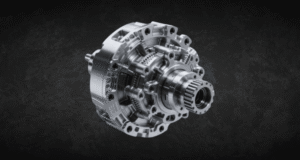
BTI engineers and manufactures a complete line of manual, semi-automatic, and fully automatic precision measurement and testing equipment for all types of transmission components
View More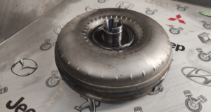
BTI engineers and manufactures a complete line of manual, semi-automatic, and fully automatic precision measurement and testing equipment for torque converters, turbines, dampers, stators, and all related assemblies and components
View More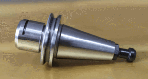
BTI engineers and manufactures both traditional spindled tool holder balancers and a patented (US Patent Numbers 5,763,777 and 5,965,815), first-of-its-kind, spindle-less balancer
View More
BTI engineers and manufactures a complete line of manual, semi-automatic, and fully automatic precision measurement and testing equipment for tire and tire/wheel assemblies for all wheel room applications
View More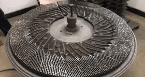
BTI engineers and manufactures a complete line of manual, semi-automatic, and fully automatic precision measurement and testing equipment for refiner plates
View More
BTI engineers and manufactures a complete line of manual, semi-automatic, and fully automatic precision measurement and testing equipment for pumps, fans, impellers, blowers, and related components
View More
BTI engineers and manufactures a complete line of manual, semi-automatic, and fully automatic precision measurement and testing equipment for all HVAC assemblies and related components
View More
BTI engineers and manufactures a complete line of manual, semi-automatic, and fully automatic precision measurement and testing equipment for hard drives, head readers, and related components
View More
BTI engineers and manufactures a complete line of manual, semi-automatic, and fully automatic precision measurement and testing equipment for flanges, yokes, and related assemblies and components
View More
To contact us regarding your project - or if you have any questions - please click the button below :
Request a QuoteGet Started
Connect with our measurement experts and get the technical guidance your application demands.