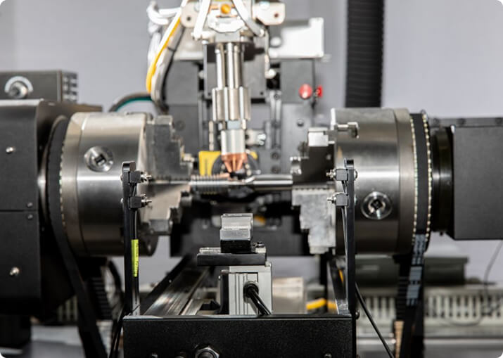

Electric Vehicle
BTI engineers and manufactures a complete line of manual, semi-automatic, and fully automatic precision measurement and testing equipment for all eDrive
View More
A tire and wheel assembly is the one rotor most people have direct experience of, and it is more complicated than it looks. It is two components, each with its own unbalance and its own geometric variation, joined in a relationship that the assembler chooses. Get that relationship right and the assembly needs less correction before any weight is attached.
Balance Technology Inc. builds balancing, uniformity and dimensional measurement equipment for tires, wheels and assembled tire-and-wheel units.
Unbalance is a mass distribution problem: a heavy spot produces a rotating force that grows with the square of speed, felt as a shimmy at road speed.
Uniformity is a stiffness and geometry problem. A tire whose stiffness varies around its circumference produces a force variation as it rolls even when it is perfectly balanced, because the contact patch is being loaded differently at different angular positions. Radial force variation is the vertical component, lateral force variation the sideways one, and conicity describes a tire’s tendency to pull to one side.
A perfectly balanced assembly with poor uniformity still rides badly. The two characteristics need measuring separately, and a line that measures only balance will pass assemblies that generate complaints.
This is the free correction, and it happens before any weight is added. Wheels have a measurable low point of radial runout; tires have a high point. Mount them so those features oppose one another and the assembly’s combined runout and force variation drop — often enough to move a marginal assembly comfortably inside tolerance.
Doing it requires marking both components and controlling the orientation at assembly, which is a process design decision rather than a machine setting. Skipping it means correcting with weight what could have been canceled with position.
A narrow wheel can be treated as a single-plane rotor. A wide one cannot: there is enough axial separation between the inner and outer rim flanges for a real couple to develop, and correcting only statically leaves a couple that produces a wobble rather than a shake. Wide, low-profile and heavy-duty assemblies are two-plane parts.
There is no material to remove, so correction is by attaching mass — clip-on weights at the rim flange, adhesive weights on the inner barrel, or a combination. Three things follow from that.
Correction resolution is limited by the discrete weight increments available. Placement accuracy matters, because a weight at the wrong angle or the wrong plane corrects the wrong thing. And retention matters over the life of the assembly, since a weight that departs leaves the vehicle worse than before it was balanced.
Radial and lateral runout on the rim, the bead seats and the assembled tire all contribute to ride quality independently of balance. Bead seating is part of this: a tire not fully or evenly seated will show runout and force variation that disappear when it is seated properly, so the assembly sequence affects the measurement.
Where a balance specification applies, it follows ISO 21940-11 from a balance quality grade, the assembly mass and the service speed. BTI publishes a free ISO 21940-11 balance tolerance calculator together with the method — grade selection, the permissible unbalance formula, allocation across two planes, and a worked example. Uniformity limits come from the vehicle manufacturer rather than from the balancing standard.
Tire and wheel lines commonly combine balancing with:
On an assembly line the uniformity station frequently does more for ride quality than the balancer does.
Layouts range from single manual stations for service and low-volume work through to fully automatic assembly lines with inflation, uniformity measurement, balancing, weight application and data collection, and vary to accommodate any production rate. For platform selection across the full range, see BTI balancing machines.
Related applications include brake rotors and drums, axles and RDU components and flanges and yokes.
How are tire and wheel assemblies balanced?
The assembly is mounted on its center bore or bolt circle, spun, and measured in two planes. Correction is by clip-on or adhesive weights applied to the rim flanges. Production lines balance and apply weights automatically; the same measurement principle applies in a tire shop, at much lower throughput.
What is the difference between static and dynamic wheel balancing?
Static balancing corrects unbalance in a single plane and addresses up-and-down vibration. Dynamic balancing corrects in two planes and also addresses the side-to-side shimmy caused by couple unbalance. A modern wheel is wide enough that dynamic balancing is the appropriate method; static alone leaves the couple uncorrected.
Why does a balanced wheel still shake?
Because unbalance is only one cause. Radial and lateral runout, tire force variation, a bent rim, worn suspension components and brake rotor thickness variation all produce vibration that balancing does not touch. A wheel that reads zero on the balancer and shakes on the road has a geometry or uniformity problem.
What is road force and how does it differ from balance?
Road force measures how much the tire’s stiffness varies around its circumference under load. A tire can be perfectly balanced and still produce a force variation as it rolls, because balance is about mass distribution and road force is about stiffness distribution. They are independent properties and both have to be within specification.
Can wheel balance be checked without removing the wheel?
On-vehicle balancers exist and spin the wheel in place, which has the advantage of including the hub, rotor and any drum in the measurement. The drawback is that they cannot separate the wheel’s contribution from the hub’s, so the correction is specific to that position on that vehicle.
Additionally, BTI’s unique ability to combine the aforementioned technologies into one fully integrated system enables our clients to reduce capital expenditures, increase product quality, and minimize floor space requirements.
Let our staff of more than 50 engineers design a configured-to-order solution for your specific requirements. Furthermore, our commercial Measurement & Testing Services Group (M&T Services) can assist with everything from prototype testing and R&D work to master certification and running small-to-medium production runs.
If you don’t see the product you are looking for, or have specific questions, please contact us.
BTI engineers and manufactures a complete line of manual, semi-automatic, and fully automatic precision measurement and testing equipment for all eDrive
View More
BTI engineers and manufactures a complete line of manual, semi-automatic, and fully automatic precision measurement and testing equipment for all turbo charger components and complete assemblies
View More
BTI engineers and manufactures a complete line of manual, semi-automatic, and fully automatic precision measurement and testing equipment for turbines, jet engines, blades, propellers, steam turbines, and other related assemblies and components weighing fractions of an ounce to 200,000 pounds
View More
BTI engineers and manufactures a complete line of manual, semi-automatic, and fully automatic precision measurement and testing equipment for all types of transmission components
View More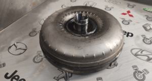
BTI engineers and manufactures a complete line of manual, semi-automatic, and fully automatic precision measurement and testing equipment for torque converters, turbines, dampers, stators, and all related assemblies and components
View More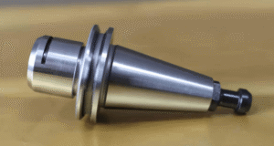
BTI engineers and manufactures both traditional spindled tool holder balancers and a patented (US Patent Numbers 5,763,777 and 5,965,815), first-of-its-kind, spindle-less balancer
View More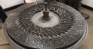
BTI engineers and manufactures a complete line of manual, semi-automatic, and fully automatic precision measurement and testing equipment for refiner plates
View More
BTI engineers and manufactures a complete line of manual, semi-automatic, and fully automatic precision measurement and testing equipment for pumps, fans, impellers, blowers, and related components
View More
BTI engineers and manufactures a complete line of manual, semi-automatic, and fully automatic precision measurement and testing equipment for all HVAC assemblies and related components
View More
BTI engineers and manufactures a complete line of manual, semi-automatic, and fully automatic precision measurement and testing equipment for hard drives, head readers, and related components
View More
BTI engineers and manufactures a complete line of manual, semi-automatic, and fully automatic precision measurement and testing equipment for all flywheels, flex plates, and related assemblies and components
View More
BTI engineers and manufactures a complete line of manual, semi-automatic, and fully automatic precision measurement and testing equipment for flanges, yokes, and related assemblies and components
View More
To contact us regarding your project - or if you have any questions - please click the button below :
Request a QuoteGet Started
Connect with our measurement experts and get the technical guidance your application demands.