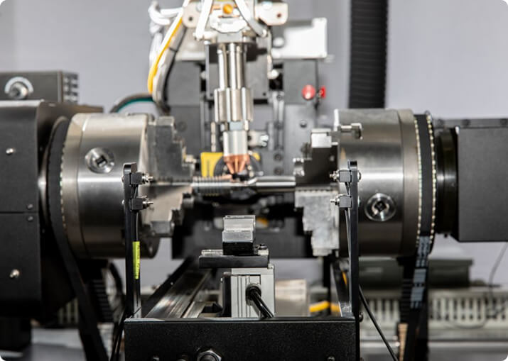

Electric Vehicle
BTI engineers and manufactures a complete line of manual, semi-automatic, and fully automatic precision measurement and testing equipment for all eDrive
View More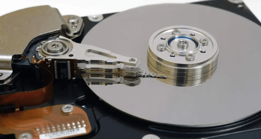
Data storage rotors are the extreme case for measurement resolution. They are small, they run fast, and the permissible unbalance that follows from those two facts is smaller than the contribution of almost any ordinary fixture. At that point the limiting factor stops being the part and becomes the machine measuring it.
Balance Technology Inc. builds precision balancing and measurement equipment for data storage components — spindle motors, platter and disc stacks, and related high-precision rotating assemblies.
Permissible unbalance scales with rotor mass and inversely with speed. A light rotor turning quickly therefore lands at a residual measured in fractions of a gram-millimeter, well below what a general-purpose industrial balancer is designed to resolve.
Two things follow. The measuring system needs a noise floor and a repeatability an order of magnitude better than the tolerance it is checking. And the fixture contribution has to be characterized rather than assumed, because at these levels the tooling can be the largest single term in the measurement.
Air-bearing supports and drives are common in this class of equipment for exactly that reason: a rolling-element support introduces more vibration than the part is allowed to have.
These assemblies are built in clean environments, and the usual correction methods are unavailable. Drilling and milling generate particulate that cannot be tolerated near a head-media interface, so correction moves to methods that produce no swarf — laser ablation, precisely placed adhesive mass, or designed balance features built into the hub.
Every one of those has a repeatability specification of its own, and on a tolerance this tight the correction process contributes meaningful error rather than simply removing it.
Head and actuator assemblies do not rotate continuously, so they do not have a balance condition in the conventional sense. What they do have is a dynamic response — resonance, settling behavior, off-track motion under acceleration — which is a different measurement requiring different equipment.
It is worth separating the two when specifying a line. Balancing equipment characterizes the spindle side. Dynamic and resonance measurement characterizes the actuator side.
Where a balance specification applies it follows ISO 21940-11 from a balance quality grade, the rotor mass and the operating speed, though this class of hardware frequently sits at or beyond the fine end of the standard’s range and may be governed by a customer specification instead. BTI publishes a free ISO 21940-11 balance tolerance calculator with the method behind it — grade selection, the permissible unbalance formula, plane allocation, and a worked example.
Work in this area commonly combines balancing with:
Measurement system capability studies matter more here than in almost any other application, because the tolerance and the measurement uncertainty are close together.
Layouts are normally engineered to the specific component and its cleanliness requirements rather than selected from a catalog. For platform selection across the full range, see BTI balancing machines, and for the measurement side see resonant frequency measurement systems.
Related applications include armatures, rotors and motor assemblies and spindle and tool holder balancing.
Why do hard drive components need balancing?
Because the disc stack turns at high speed with read heads flying microns above the surface. Unbalance produces runout that the head positioning system has to compensate for, and beyond a certain level it cannot. The tolerances are among the tightest in any balancing application.
How are disc stacks balanced?
As assemblies, on their own spindle, at or near operating speed. Correction is made in very small increments, typically by adding or removing tiny masses at defined locations on the clamp or hub. The quantities involved are small enough that handling and cleanliness become part of the process.
What makes this application different from conventional balancing?
Scale and environment. The residual unbalance permitted is orders of magnitude smaller than on an automotive part, the correction increments are correspondingly tiny, and the whole operation has to happen without introducing particulate contamination. The physics is the same; the practice is not.
Can a disc stack be balanced after assembly into the drive?
No. Once the stack is enclosed there is no access for correction. Balance is established during assembly of the stack, which is why the balancing operation is integrated into the assembly process rather than performed afterward.
What else is measured on these assemblies?
Runout, axial and radial, and the dynamic response of the stack at speed. Because the head-to-disc spacing is the critical dimension, anything that moves the disc surface out of plane matters as much as mass unbalance does.
Additionally, BTI’s unique ability to combine the aforementioned technologies into one fully integrated system enables our clients to reduce capital expenditures, increase product quality, and minimize floor space requirements.
Let our staff of more than 50 engineers design a configured-to-order solution for your specific requirements. Furthermore, our commercial Measurement & Testing Services Group (M&T Services) can assist with everything from prototype testing and R&D work to master certification and running small-to-medium production runs.
If you don’t see the product you are looking for, or have specific questions, please contact us.
BTI engineers and manufactures a complete line of manual, semi-automatic, and fully automatic precision measurement and testing equipment for all eDrive
View More
BTI engineers and manufactures a complete line of manual, semi-automatic, and fully automatic precision measurement and testing equipment for all turbo charger components and complete assemblies
View More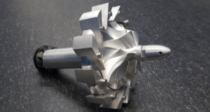
BTI engineers and manufactures a complete line of manual, semi-automatic, and fully automatic precision measurement and testing equipment for turbines, jet engines, blades, propellers, steam turbines, and other related assemblies and components weighing fractions of an ounce to 200,000 pounds
View More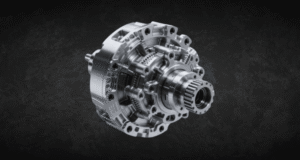
BTI engineers and manufactures a complete line of manual, semi-automatic, and fully automatic precision measurement and testing equipment for all types of transmission components
View More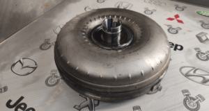
BTI engineers and manufactures a complete line of manual, semi-automatic, and fully automatic precision measurement and testing equipment for torque converters, turbines, dampers, stators, and all related assemblies and components
View More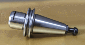
BTI engineers and manufactures both traditional spindled tool holder balancers and a patented (US Patent Numbers 5,763,777 and 5,965,815), first-of-its-kind, spindle-less balancer
View More
BTI engineers and manufactures a complete line of manual, semi-automatic, and fully automatic precision measurement and testing equipment for tire and tire/wheel assemblies for all wheel room applications
View More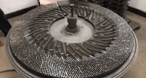
BTI engineers and manufactures a complete line of manual, semi-automatic, and fully automatic precision measurement and testing equipment for refiner plates
View More
BTI engineers and manufactures a complete line of manual, semi-automatic, and fully automatic precision measurement and testing equipment for pumps, fans, impellers, blowers, and related components
View More
BTI engineers and manufactures a complete line of manual, semi-automatic, and fully automatic precision measurement and testing equipment for all HVAC assemblies and related components
View More
BTI engineers and manufactures a complete line of manual, semi-automatic, and fully automatic precision measurement and testing equipment for all flywheels, flex plates, and related assemblies and components
View More
BTI engineers and manufactures a complete line of manual, semi-automatic, and fully automatic precision measurement and testing equipment for flanges, yokes, and related assemblies and components
View More
To contact us regarding your project - or if you have any questions - please click the button below :
Request a QuoteGet Started
Connect with our measurement experts and get the technical guidance your application demands.