
Electric Vehicle
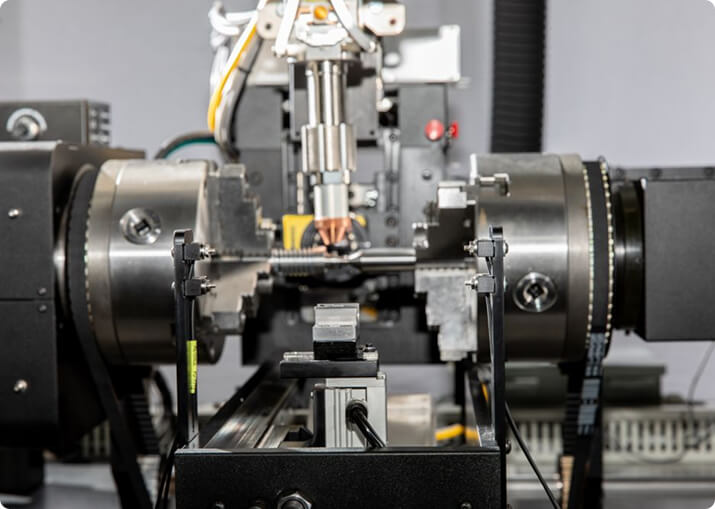
BTI engineers and manufactures a complete line of manual, semi-automatic, and fully automatic precision measurement and testing equipment for all eDrive
View More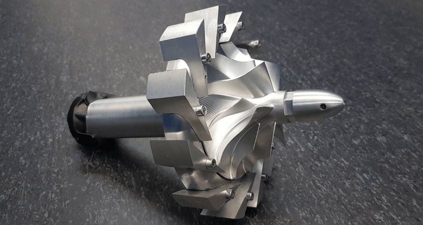
A bladed rotor is different from every other rotor on a balancing floor in one decisive way: most of its mass sits at the largest radius, and it is removable. That means the balance condition is largely decided before the rotor reaches a balancing machine, by how the blades are weighed and where each one is placed.
Balance Technology Inc. builds balancing, spin testing, crack detection and dimensional measurement equipment for turbine and compressor rotors, jet engine components, individual blades, propellers and fans.
Blades are not matched by mass alone. What matters is the moment each blade contributes about the rotor axis — mass multiplied by the radius of its center of gravity — because two blades of identical mass with different center-of-gravity positions do not contribute equally.
Moment weighing measures that quantity directly, and the blade set is then distributed around the disc to minimize the residual unbalance of the assembly before any correction is applied. A well-optimized distribution can leave a rotor close enough to tolerance that correction becomes a trim rather than a repair. A poor one leaves a residual no correction plane can comfortably absorb.
Gas turbine and jet engine rotors commonly operate above their first bending critical speed. A rotor that bends in service is a flexible rotor, and ISO 21940 handles it separately for a reason: two-plane low-speed balancing does not describe it. The bow that appears at speed creates unbalance that simply is not present on a low-speed machine.
Flexible rotors need either multi-plane balancing informed by their mode shapes, or balancing at or near service speed, or both. Deciding which applies is a rotordynamic question answered from the rotor geometry and the operating range — not something to infer from how a part looks.
Airfoils are aerodynamic surfaces and structural members. Material generally cannot come off them. Correction therefore has to happen somewhere the designer provided for it: balance lands or rims machined into the disc, threaded balance rings, trim weights at designed locations, or selective blade repositioning.
That constraint is why blade distribution carries so much weight in the process. When the only correction planes available are small and tightly limited, the assembly has to arrive nearly balanced.
Balance quality grades for turbine and aerospace rotors sit at the demanding end of ISO 21940-11 — frequently G2.5 or finer, against G6.3 for a pump impeller and G16 for a driveshaft. Because permissible unbalance scales inversely with speed, a high-speed rotor at a fine grade produces a very small permissible residual, and the measurement system has to resolve it against tooling and drive contributions of the same order.
BTI publishes a free ISO 21940-11 balance tolerance calculator together with the method — grade selection, the permissible unbalance formula, plane allocation, and a worked example.
Rotating components in this sector are frequently required to demonstrate integrity as well as balance: overspeed proof, burst margin, low-cycle fatigue, and creep or growth measurement. That work happens in a containment-rated spin pit rather than on a balancing machine, and it is a different discipline with different safety engineering.
BTI builds spin test systems for this work alongside balancing equipment, which matters where the same part has to be characterized both ways.
Rotating aerospace and power generation hardware is rarely accepted on balance alone. Depending on the component and the failure modes being controlled, equipment for this application also covers:
Traceability of measurement to a calibrated standard is normally a contractual requirement rather than a preference.
Layouts range from single manual stations for overhaul and repair work through to automated cells for series production, and vary to accommodate any production rate. For platform selection across the full range, see BTI balancing machines.
Related applications include pumps, fans, impellers and blowers and turbochargers and superchargers.
How are turbine rotors and blades balanced?
Blades are moment weighed and distributed around the disc before the rotor is assembled, so the assembly starts close to balance. The assembled rotor is then balanced conventionally, and for high-speed applications it may be balanced at multiple speeds or at speed in a vacuum chamber.
What is blade moment weighing and why does it come first?
Each blade is weighed with its center of gravity taken into account, producing a moment rather than a simple mass. The blades are then arranged around the disc so their moments cancel as nearly as possible. Doing this first means the assembled rotor needs far less correction, which matters because turbine discs have very little material that can be removed.
Why are some turbine rotors balanced as flexible rather than rigid?
Because their operating speed is above their first critical speed. A rotor that passes through a critical bends, and its mass distribution when bent is not the same as when straight. Balancing such a rotor at low speed corrects a condition it never runs in. These rotors need balancing at or near service speed, sometimes in several planes at several speeds.
How is a turbine rotor corrected when material cannot be removed?
Through features designed in for the purpose — balance rings, weighted bolts, lock wires, or defined correction lands on the disc rims. Blade rearrangement is also a correction method in its own right. What is not acceptable is removing material from an airfoil or a highly stressed disc section.
Are propellers balanced the same way as turbine rotors?
The principle is shared but the practice differs. A propeller is balanced both statically and dynamically, and blade track and pitch matter as much as mass distribution. Aerodynamic asymmetry produces vibration that mass balancing cannot correct, so track and pitch are checked alongside balance.
What is spin testing and how does it relate to balancing?
Spin testing runs a rotor to or beyond its service speed, often to validate containment or to prove structural integrity. It is a different test from balancing, but the two are frequently done in the same machine because both require a rotor spun safely at speed with instrumentation on it.
Traditional equipment for this application includes balancing equipment, dimensional gages, moment systems, eddy current crack detection systems, surface finish measurement equipment, functional test stands, resonant frequency measurement systems, destructive testers, and specialized test systems.
Additionally, BTI’s unique ability to combine the aforementioned technologies into one fully integrated system enables our clients to reduce capital expenditures, increase product quality, and minimize floor space requirements.
Let our staff of more than 50 engineers design a configured-to-order solution for your specific requirements. Furthermore, our commercial Measurement & Testing Services Group (M&T Services) can assist with everything from prototype testing and R&D work to master certification and running small-to-medium production runs.
If you don’t see the product you are looking for, or have specific questions, please contact us.
BTI engineers and manufactures a complete line of manual, semi-automatic, and fully automatic precision measurement and testing equipment for all eDrive
View More
BTI engineers and manufactures a complete line of manual, semi-automatic, and fully automatic precision measurement and testing equipment for all turbo charger components and complete assemblies
View More
BTI engineers and manufactures a complete line of manual, semi-automatic, and fully automatic precision measurement and testing equipment for all types of transmission components
View More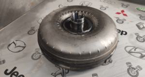
BTI engineers and manufactures a complete line of manual, semi-automatic, and fully automatic precision measurement and testing equipment for torque converters, turbines, dampers, stators, and all related assemblies and components
View More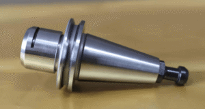
BTI engineers and manufactures both traditional spindled tool holder balancers and a patented (US Patent Numbers 5,763,777 and 5,965,815), first-of-its-kind, spindle-less balancer
View More
BTI engineers and manufactures a complete line of manual, semi-automatic, and fully automatic precision measurement and testing equipment for tire and tire/wheel assemblies for all wheel room applications
View More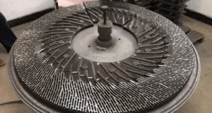
BTI engineers and manufactures a complete line of manual, semi-automatic, and fully automatic precision measurement and testing equipment for refiner plates
View More
BTI engineers and manufactures a complete line of manual, semi-automatic, and fully automatic precision measurement and testing equipment for pumps, fans, impellers, blowers, and related components
View More
BTI engineers and manufactures a complete line of manual, semi-automatic, and fully automatic precision measurement and testing equipment for all HVAC assemblies and related components
View More
BTI engineers and manufactures a complete line of manual, semi-automatic, and fully automatic precision measurement and testing equipment for hard drives, head readers, and related components
View More
BTI engineers and manufactures a complete line of manual, semi-automatic, and fully automatic precision measurement and testing equipment for all flywheels, flex plates, and related assemblies and components
View More
BTI engineers and manufactures a complete line of manual, semi-automatic, and fully automatic precision measurement and testing equipment for flanges, yokes, and related assemblies and components
View More
To contact us regarding your project - or if you have any questions - please click the button below :
Request a QuoteGet Started
Connect with our measurement experts and get the technical guidance your application demands.