Automotive
Balance Technology Inc. builds balancing machines and measurement systems for automotive manufacturing — crankshafts and driveshafts, brake rotors and drums, torque converters and flywheels, turbochargers, engine cooling modules, and electric-drive rotors and axles. BTI has been designing this equipment in Whitmore Lake, Michigan since 1968.
Automotive work splits into two very different buying problems, and BTI builds for both. A production line needs a machine engineered around one part family, integrated into the line, holding a balance tolerance at takt time for years. A repair, remanufacturing or aftermarket shop needs a capable machine that covers a range of parts, quoted from a standard model and shipped on a standard lead time. The first starts from a part print. The second starts from a model number.
What BTI Balances in Automotive
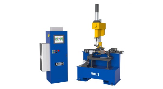
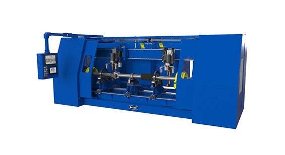
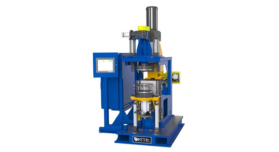
BTI balancing machines are built on four platforms — VNR (vertical non-rotator), H (horizontal cradle), VR (vertical rotator) and P (platform suspension) — plus spinners and test stands. The platform follows the part geometry and how it has to be held; the correction method follows the material and where there is room to add or remove mass.
| Component | Typical platform | Correction method |
|---|---|---|
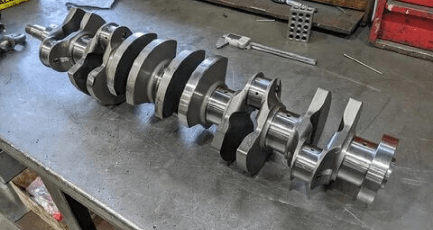
| Crankshafts | H | Drill, mill |
| Driveshafts and propeller shafts | H | Weld-on weight |
| Brake rotors and drums | VNR, VR | Mill, drill |
| Flywheels and flex plates | VNR | Drill, mill |
| Torque converters | VR | Weld-on weight |
| Turbocharger wheels and assemblies | P, VR | Mill, grind |
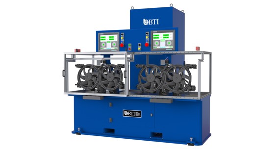
| Engine cooling modules | P | Weight-add |
| Armatures, rotors and motor assemblies | H | Mill, drill, weight-add |
| Axles, RDUs and reducer components | P, VR, H | Drill, weight-add |
| Transmission components | VR, H | Drill, mill |
| Clutches and pressure plates | VNR, VR | Drill, weight-add |
| Wheel and tire assemblies | VNR, VR | Clip-on weight |
How a Machine Gets Sized
A BTI machine designation names a platform and a class. A P-5 is the platform suspension base, class 5. The number is a class, not a part weight limit — it describes the size and load envelope of the base.
Sizing works from the tooling and the part together, not the part alone. Tooling is not specified until the part prints are reviewed and the fixture is concepted, and the heavier the tooling-plus-part assembly is relative to the class, the less repeatable the measurement becomes. A shop that needs one machine to cover a wide range of parts, and does not need tight repeatability, can run a much broader weight range on a given class than a production program can.
Tell BTI the part weight and BTI will name a class the same day. See BTI machine platforms for the full platform and class architecture.
Balance Grade and Tolerance
Automotive balance tolerances are set by ISO 21940-11, which superseded ISO 1940-1. The standard assigns a balance quality grade G, and the permissible residual specific unbalance follows from that grade and the service speed:
eper = (G × 60) ÷ (2π × n)
where eper is permissible residual specific unbalance in g·mm/kg, G is the balance quality grade in mm/s, and n is the service speed in rev/min. Permissible residual unbalance is then U = eper × m, divided across the correction planes.
| Grade | Typical automotive components |
|---|---|
| G 40 | Car wheels, wheel rims, wheel sets |
| G 16 | Driveshafts and cardan shafts with special requirements |
| G 6.3 | Fans, flywheels, pump impellers, normal electric armatures |
| G 2.5 | Turbochargers, machine-tool drives, special electric armatures |
Work out a specific tolerance with the ISO balance tolerance calculator.
Electrified Driveline
Electric drive units move the balancing problem rather than removing it. Rotor stacks turn far faster than a combustion crankshaft, so the same residual unbalance produces much larger forces and the tolerance tightens accordingly. Motor rotors, reducer and e-axle shafts, and rear drive units all carry balance requirements, and NVH expectations are higher because there is no engine noise to mask them.
BTI builds balancers and measurement systems for armatures, rotors and motor assemblies, for axles and RDU components, and for the transmission and reducer components between them. See electric vehicle applications.
A representative example: a motor armature balanced inside its stator to a G 2.5 balance grade, with correction by drilling on the end plates. The assembly cannot be separated for balancing, so the machine has to measure and correct the rotor in place.
Correction Methods
| Method | Where it fits |
|---|---|
| Drill | Cast and forged parts with material available to remove |
| Mill | Controlled removal on a defined correction band |
| Grind | Hardened or finished surfaces |
| Weld-on weight | Driveshafts and torque converters, adding rather than removing mass |
| Clip-on or press-on weight | Wheel and tire assemblies |
| Adhesive and applied weight | Cooling modules, plastics and assemblies |
Standards
BTI certifies machines to ISO 21940, SAE International balancing specifications, and DIN specifications. Where a program carries a measurement system capability requirement, BTI evaluates the part and the process first, then confirms what is achievable and commits to it in the machine specification.
Frequently Asked Questions
What balance grade does an automotive crankshaft need?
Crankshaft tolerances are set by the engine program rather than by a universal figure. ISO 21940-11 places most reciprocating engine components between G 16 and G 6.3, with the specific tolerance following from the service speed and the rotor mass.
Can one balancing machine cover more than one part?
Yes, within a class. How wide that range can be depends on the tooling and on how much repeatability the application requires. MRO and remanufacturing shops routinely run a broad part range on a single class.
Does BTI rebuild or retrofit existing balancing machines?
Yes, including machines built by other manufacturers. See BTI rebuilds and retrofits, competitor rebuilds and retrofits, and PC upgrades for machines still mechanically sound.
What information does BTI need to quote an automotive balancer?
The part print, the part weight, the service speed, the balance tolerance if one is specified, and the required production rate.
How are BTI lead times quoted?
Lead times are quoted in weeks at the time of quotation. They move with current backlog, so BTI confirms the schedule for a specific machine as part of the quote rather than publishing a fixed figure.
What is the difference between a standard model and a configured-to-order machine?
A standard model is quoted from the BTI model number and built to a defined configuration. A configured-to-order machine starts from a proven BTI platform and the part print, with tooling concepted for the specific part and the platform configured around it.








Connect with us
To contact us regarding your project - or if you have any questions - please click the button below :
Request a QuoteGet Started
Get in touch with us. We're here to assist you.
Connect with our measurement experts and get the technical guidance your application demands.